4
MaxxBass User Guide
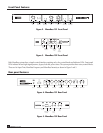
Front Panel Features
Input Trim
Knob
Input Signal
Indicators
Bypass Button
and Indicator
MaxxBass Intensity
Knob
MaxxBass Frequency
Knob
Lock Button
and Indicator
Power Button
and Indicator
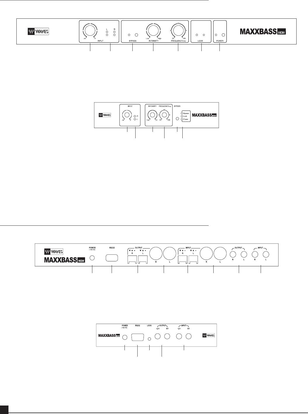
Figure 2. MaxxBass 101 Front Panel
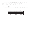
Input Trim
Knob
Input Signal
Indicators
Bypass
Button
MaxxBass
Intensity
Knob
MaxxBass
Frequency
Knob
Bypass
Lock
Power
Indicators
Figure 3. MaxxBass 102 Front Panel
Both MaxxBass systems have a simple control interface requiring only a few control knobs and indicator LEDs. Front panel
LEDs indicate left and right signal presence, bypass, lock and power status. The system provides three rotary control knobs.
These are for Input Trim, MaxxBass Frequency and MaxxBass Intensity as shown in Figure 2 and 3.
Rear panel Features
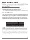
AC Input RS232 Serial
Connector
Wire Terminal
Output
XLR Output Wire Terminal
Input
XLR Input TS/TRS Output TS/TRS Input
Figure 4. MaxxBass 101 Rear Panel
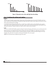
RS232 Serial
Connector
Lock
Button
AC Input Input
(RCA)
Output
(RCA)
Figure 5. MaxxBass 102 Rear Panel


