


1
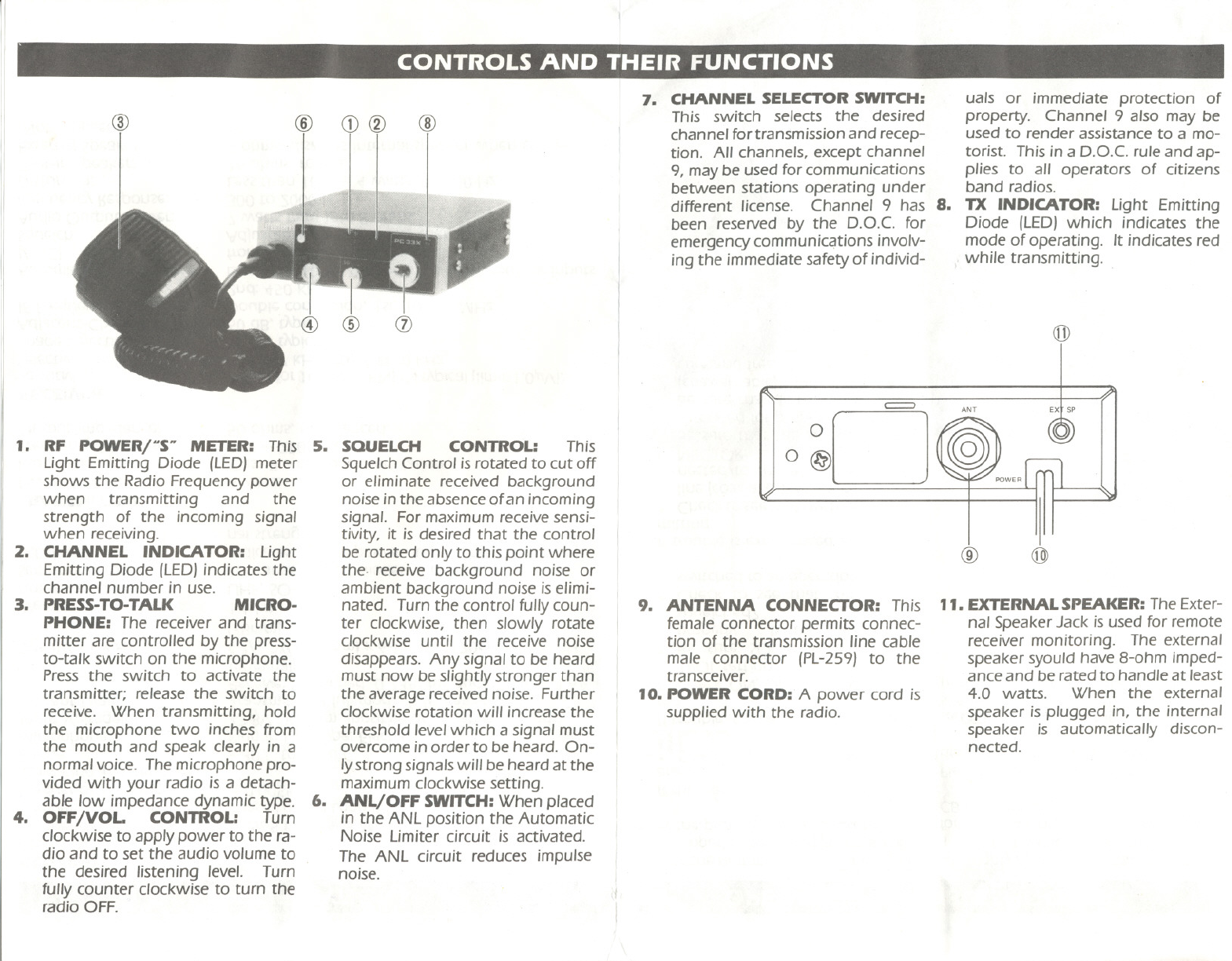
7. CHANNEL SELECTORSWITCH: uals or immediate protection of
@ @ CD@ @
I This switch sele~ts. the desired property. Channe.I 9 also may be
. channelfortransmissionand recep- used to render assistanceto a mo-
tion. All channels, except channel torist. This in a D.O.C. rule and ap-
9, may be used for communications plies to all operators of citizens
between stations operating under band radios.
different license. Channel 9 has 8. TX INDICATOR: Light Emitting
been reseNed by the D.O.C. for Diode (LED) which indicates the
emergency communic~tions involv- mode of operating. It indicates red
ing the immediate safety of individ-
f while transmitting.
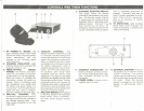
1. RF POWER/uS" METER: This
Light Emitting Diode (LED)meter
shows the Radio Frequency power
when transmitting and the
strength of the incoming signal
when receiving.
2. CHANNEL INDICATOR: Light
Emitting Diode (LED)indicates the
channel number in use.
3. PRESS-TO-TALK MICRO-
PHONE: The receiver and trans-
mitter are controlled by the press-
to-talk switch on the microphone.
Press the switch to activate the
transmitter; release the switch to
receive. When transmitting, hold
the microphone two inches from
the mouth and speak clearly in a
normal voice. The microphone pro-
vided with your radio is a detach-
able Iow impedance dynamic type.
4. OFF/VOL. CONTROL: Turn
clockwise to apply power to the ra-
dio and to set the audio volume to
the desired listening level. Turn
fully counter clockwise to turn the
radio OFF.
5. SQUELCH CONTROL: This
Squelch Control is rotated to cut off
or eliminate received background
noise in the absence ofan incoming
signal. For maximum receive sensi-
tivity, it is desired that the control
be rotated only to this point where
the. receive background noise or
ambient background noise iselimi-
nated. Turn the control fullycoun-
ter clockwise, then slowly rotate
clockwise until the receive noise
disappears. Any signal to be heard
must now be slightlystronger than
the average received noise. Further
clockwise rotation will increase the
threshold levelwhich a signal must
overcome inorder to be heard. On-
Iystrong signals willbe heard at the
maximum clockwise setting.
6. ANL/OFF SWITCH:When placed
in the ANL position the Automatic
Noise Limiter circuit is activated.
The ANL circuit reduces impulse
noise.
(j])
~
ANT
Ext Sp
0
O@
@
@
9. ANTENNA CONNECTOR: This
female connector permits connec-
tion of the transmission line cable
male connector (PL-259) to the
transceiver.
10. POWER CORD: A power cord is
supplied with the radio.
11. EXTERNALSPEAKER:The Exter-
nal Speaker Jack isused for remote
receiver monitoring. The external
speaker syould have 8-ohm imped-
ance and be rated to handle at least
4.0 watts. When the external
speaker isplugged in, the internal
speaker is automatically discon-
nected.