


,
IN STAI.LATI ON
MOBILE INSTALLATION
Plan the location of the radio and micro-
phone bracket before starting installation.
Select a location that is convenient for op-
eration and does not interfere with the
driver or passenger in the vehicle. The mic
hanger bracket should be securely
fastened to a solid surface using the self-
tapping screws which are provided. The
button on the back of the radio will slide
into the mic hanger to hold it securely in
place.
Mobile Antenna
Since the maximum allowable power out-
put of the transceiver is limited by the
D.O.C, the antenna isa veryimportant fac-
tor affecting transmission distance. The
magnetic mount base and screw-in teles-
copic antenna willprovide maximum range
when properly installed.
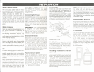
Screw the antenna into the base. Place the
base on a flat metallic area of your vehicle
roof. The center of the roof isideal for 3600
transmission. Feed the coaxial cable thru a
window or door. With the battery pack off,
connect the antenna to the bottom of the
unit.
Ifanother external antenna is desired con-
sult your local CB Dealer for a com-
patible model. You have purchased a
superior quality transceiver. Don't diminish
its performance by installing an inferior
antenna.
Only a properly matched antenna system
will allow maximum power transfer from
the 50-ohm transmission line to the radiat-
ing element. We recommend that you
have your system checked with an SWR
meter when installing your antenna. Your
local dealer is qualified to assist you in
the selection an installation of a proper
antenna to meet your application:
requirements.
Connecting the Power
Connect the power cord to the jack on the
bottom of the unit (battery pack must be
removed). Plug the cord into the cigarette
lighter ofyour vehicle. The PRO 31Oe may I
also be connected directly to the fuse
block with the proper wiring (not]
included).
IMPORTANT - The cigarette lighter plug
is designed to be used with negative
ground vehicles. Do not attempt to oper-
ate the unit with the power cord con-
nected to a positive ground vehicle.
Ground Information
Most newer cars and small trucks use a ne-
gative ground system, while some older
cars and some newer, larger trucks may use
a positive ground system. A negative
ground system is generally identified by the I
"-" battery terminal being connected to
the vehicle motor block. Ifyou cannot de-
termine the polarity ofyour vehicle, consult
your vehicle dealer for information.
Positive Ground System
Ifyou are operating on a positive ground
system, the unit must be wired directly to
the fuse block. Connect the black lead
from the radio to the negative" -" bat-
tery terminal or other convenient point
and connect the red power lead to the
chassis or vehicle frame, or the positive
" + " terminal of the battery.
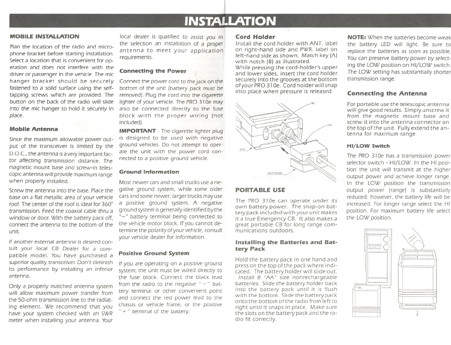
Cord Holder
Install the cord holder with ANT. label
on right-hand side and PWR. label on
left-hand side as shown. Match key (AJ
with notch (BJas illustrated.
While pressing the cord-holder's upper
and lower sides, insert the cord holder
securely into the grooves at the bottom
ofyour PRO 31De. Cord holder will snap
into place when pressure is released.
PORTABLE USE
The PRO 31 De can operate under its
own battery power. The snap-on bat-
tery pack included with your unit makes
it a true Emergency CB. It also makes a
great portable CB for long range com-
munications outdoors.
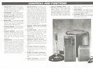
Installing the Batteries and Bat-
tery Pack
Hold the battery pack in one hand and
press on the top of the pack where indi-
cated. The battery holder will slide out.
Install 8 "AA" size nonrechargeable
batteries. Slide the battery holder back
into the battery pack until it is flush
with the bottom. Slide the battery pack
onto the bottom of the radio from left to
right until it snaps in place. Make sure
the slots on the battery pack and the ra-
dio fit correctly.
NOTE: When the batteries become weak
the battery LED will light. Be sure to
replace the batteries as soon as possible.
Youcan preseNe battery power by select-
ing the LOWposition on HI/LOW switch.
The LOWsetting has substantially shorter
transmission range.
Connecting the Antenna
For portable use the telescopic antenna
will give good results. Simply unscrew it
from the magnetic mount base and
screw it into the antenna connector Gn
the top of the unit. Fully extend the an-
tenna for maximum range.
HI/LOW Switch
The PRO 31De has a transmission power
selector switch - HI/LOW. In the HI posi-
tion the unit will transmit at the higher
output power and achieve longer range.
In the LOW position the transmission
output power (range) is substantially
reduced; however, the battery life will be
increased. For longer range select the HI
position. For maximum battery life select
the LOW position.
J