


CSE-RACK14U Mini-Rack Cabinet User’s Guide
4-2
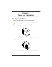
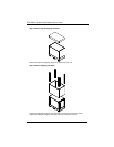
Supporting Stands
The mini-rack cabinet has support stands at each corner that can be screwed down to
support and stabilize the cabinet. Before installing equipment in the mini-rack cabinet,
be sure to secure it with the support stands first. When moving the cabinet, screw up the
support stands to free the casters for movement.
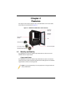
4-2 Cabinet Door
The CSE-RACK14U mini-rack cabinet comes with removable front and rear doors. The
door contains a hexagonal screen for air cooling purposes and is secured by a locking
latch. A rack grounding wire is attached to the door to prevent static discharge when
touched.
When equipment is installed and in use in the mini-rack cabinet, make sure this door is
closed for cooling, safety and security purposes.
Removing the Door
The door of the CSE-RACK14U mini-rack cabinet can be removed using the following
procedure.
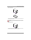
Removing the Cabinet Door
1. Push the lever in the door hinge to release the door.
2. Detach the ground wire from the door.
3. Lift off the door and put it in a secure and safe place while it is disconnected from
the cabinet.
Door Lock
The door of your CSE-RACK14U mini-rack cabinet contains a secure lock for securing
the cabinet from intrusion.
Door Filter (Optional)
An optional door filter is available for the CSE-RACK14U mini-rack cabinet.
4-3 Gauge Label Indicators
Gauge label indicators are placed on both internal sides of the cabinet, front and back,
for measurement and installation of equipment into the cabinet. These assist in proper
sizing and fitting of industry standard equipment into the rack.