


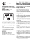
CONNECTING THE AS2 (see
Illustration 4
)
IMPORTANT: Make sure all source components and power amplifiers are
turned OFF before making any connections.
Do not plug the AS2 power supply into a wall outlet until all connections
have been made.
1. Determine which amplifier will be the main (default) amplifier and which is
the remote (sensing/switching) amplifier. In most cases the Main amplifier
will have program that is continuous or active most of the time, such as a
whole-home audio system amplifier. The Remote amplifier will have
program material the user will be watching or listening to for a relatively short
time,such as a paging system amplifier or a local TV set’s speaker outputs.
2.Connect the left & right speaker outputs of the main amplifier to the AS2’s
Input A terminals; connect the left & right speaker outputs of the remote
amplifier to the AS2’s Input B terminals.
Note: The AS2 can be used with amplifiers up to 100 watts RMS/channel.
3.Connect the AS2’s left & right Outputs to the local zone speakers.
4. Connect the included PS-1 power supply to the AS2’s 12V DC jack and plug
it into a non-switched AC outlet that supplies continuous current.
• If you’re using more than one Sonance Industry Upgrade component you
can power it from the AS2’s power supply by connecting a cable with
standard 2.1mm internal diameter connectors between the AS2’s Loop
jack and the other component’s 12V DC jack.
5.The amount of time it takes for the AS2 to revert back to Input A after the
signal to Input B has stopped is user-adjustable by the B To A Delay Adjust
control.Turning the control clockwise increases the delay time.
• The minimum delay time is 3 seconds; the maximum is 3 minutes.
6.The amount of Input B voltage required to switch the AS2 from Input A to
Input B is user-adjustable by the Trigger Sensitivity control. Turning the
control clockwise increases the trigger sensitivity (requires less voltage to
trigger the inputs to change).
• The minimum voltage required for triggering is 5mV;the maximum is 4.5V.
INSTRUCTION MANUAL
AS2 and AS2/S INDUSTRY UPGRADE
AUTOMATIC SECONDARY SPEAKER SOURCE SELECTOR
+L– –R+
CONTROL OUTPUT
12VDC 100mA
INPUT A INPUT B
OUTPUT
AUTO SWITCH,
SPEAKER LEVEL
+L– –R+ +L– –R+
IN
OUT
12VDC
150mA
TRIGGER
SENSITIVITY
B TO A
DELAY
AS2
+ –
Output
Input A
Active
Indicator
Power
Supply
Connections
Input B
Active
Indicator
Trigger
Sensitivity
Adjustment
Switching
Delay Time
Adjustment
Remote
Input
Main
Input
Control
Output
Illustration 4: AS2 Connections and Controls
2
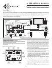
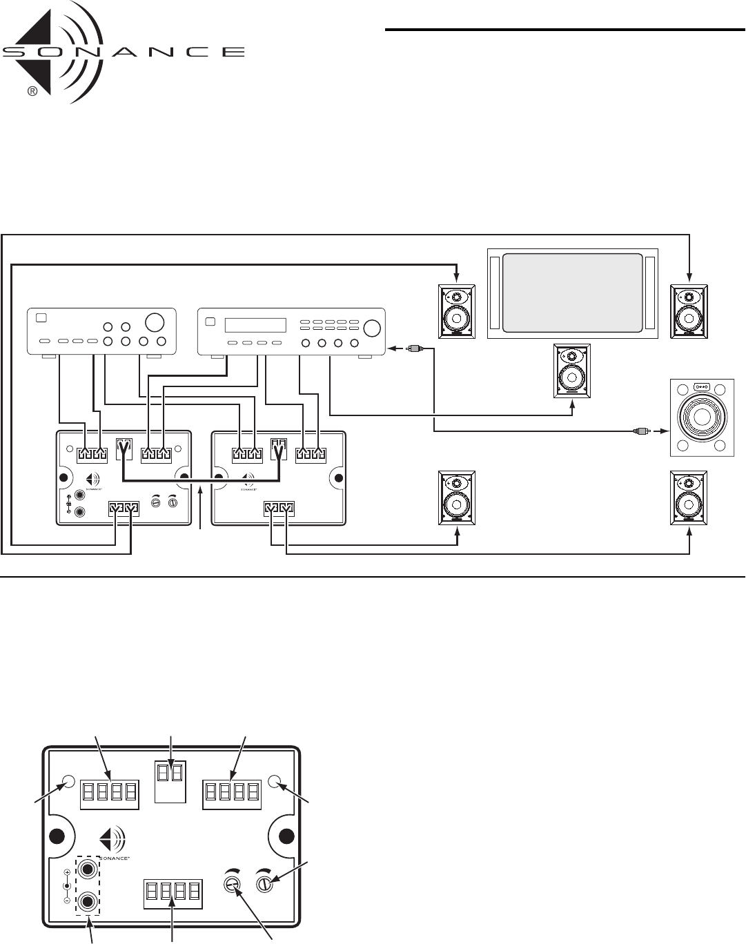
In a Home Theater (see
Illustration 3
)
The AS2 and AS2/S can be used to switch speakers in a home theater system between background music reproduction and dedicated home theater duties.In the
example below,an AS2 is used to switch the front left & right speakers from background music to home theater application,while an AS2/S slave unit switches
the surround speakers from background music to home theater surround channel application. The background music amplifier is the main input (Input A),
while the surround sound receiver is the remote input (Input B) — when it outputs a signal the AS2 and AS2/S send its signal to the speakers.
+L– –R+
CONTROL OUTPUT
12VDC 100mA
INPUT A INPUT B
OUTPUT
AUTO SWITCH,
SPEAKER LEVEL
+L– –R+ +L– –R+
IN
OUT
12VDC
150mA
TRIGGER
SENSITIVITY
B TO A
DELAY
AS2
+ –
CONTROL INPUT
12VDC 100mA
SLAVE,
SPEAKER LEVEL
+L– –R+
INPUT A INPUT B
OUTPUT
+L– –R+ +L– –R+
AS2
/
S
+ –
Front
Speaker
Outputs
Speaker B
Outputs
Speaker A
Outputs
Surround
Speaker
Outputs
Center
Speaker
Output
Left
Speaker
Left
Surround
Speaker
Powered
Subwoofer
Right
Surround
Speaker
Center
Speaker
Right
Speaker
TV/Monitor
Surround Sound
Receiver
Background Music
Amplifier
AS2
Selector
AS2/S
Selector
From Control Output
To Control Input
Illustration 3: Switching Speakers in a Home Theater System