Choose a mounting location. The SRA-40 antenna must be mounted horizontally in a location
that is open and has a clear view of the sky. It must be mounted away from any metal objects or
other structures that could block the line-of-sight reception of the satellite signal. The height of the
antenna is not as important as having a clear view of the horizon. To determine the best location for
the SRA-40, hold the Satellite Shooter template (back page) horizontally at the chosen mounting
location and follow the instructions on the template. Scan a full circle with the Shooter to make
sure no obstacles block the antenna’s view of the sky from overhead.
The Mounting Flange requires a flat, not curved surface, or the antenna can be mounted on
the 1”-14 thread end of a marine antenna extension mast or a Shakespeare Style 4720 Rail Mount
(each sold separately). The antenna’s cable can be routed through a hole in the mounting surface,
through the Mounting Flange, or through the extension mast.
IMPORTANT: When mounting to a flat surface using the mounting flange and gasket, orient
the Mounting Flange so that its cable exit faces the rear of the vessel or vehicle, away from
oncoming wind due to normal vessel or vehicle motion. Mount the SRA-40 so that it does not
interfere with safe operation of the vessel or vehicle.
In choosing how and where to mount the antenna, consider the accessibility of the area
underneath, and whether the area is clear of any wires or other obstructions. Choose a convenient
pathway for running the coax cable as far as possible from other electrical cables.
If the distance between the antenna and your Satellite receiver is more than 25 feet, special
Shakespeare cable kits are available (see Optional Accessories, back page). Acquire the appropriate
kit before proceeding.
SURFACE MOUNTING
If you are attaching the antenna directly to a flat surface, the cable with its connector attached
can be routed through a 9/16” hole drilled in the mounting surface.
Do not cut the cable and do not remove the connector.
Step 1: Drill a 9/16" mounting hole. For mounting surfaces from 1/4" to 1" thick, use the
extension shaft (supplied).
· Route the 6" antenna lead with TNC female connector through the center of the extension
shaft.
· Thread the Extension Shaft onto the existing antenna shaft and tighten.
Step 2: Pass the connector, cable, and shaft (if used) from the SRA-40 through the hole.
SRA-40 antenna
Rubber O-ring
Mounting Flange
Knockouts (3@120
o
)
(USE ONLY ONE)
DO NOT CUT THE CABLE OR REMOVE THE CONNECTOR!
Step 3: Secure the antenna to the mounting surface with the supplied retaining nut and lock washer
(see Figures 2 & 3). A small bead of RTV around the outer edge of the antenna base is recommended
to insure a watertight seal.
Skip to “Completing the installation” on page 5.
PEDESTAL MOUNTING
If you are attaching the antenna/pedestal assembly to a flat surface, the cable with its connector
attached can be routed through a 9/16” hole drilled in the mounting surface, or passed through the
Mounting Flange. Do not cut the cable and do not remove the connector.
If you are running the cable through the mounting surface:
Step 1: Drill a 9/16” center hole for the antenna cable. When drilling fiberglass surfaces, use a small
backup block of scrap wood to control push-through splintering. Use caution to avoid drilling through
or near fuel lines, fuel tanks, hydraulic lines, or electrical wiring.
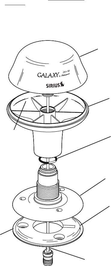
Step 2: Attach the Thread Adapter to the SRA-40 antenna; then attach the Mounting Flange to the
Thread Adapter and place the Mounting Gasket in the Mounting Flange (refer to the diagram at right).
Orient the antenna so that the Galaxy
®
name faces forward (or otherwise as you prefer). Mark a pencil
line on the flange and the mouting surface to serve as an index in step 6b.
Step 3: While holding the Mounting Gasket to the surface, lift off the assembly and use the Mounting
Gasket as a template to mark locations for the mounting screws.
Step 4: The supplied mounting screws will accommodate most surfaces. If you find them too long,
too short, or otherwise unsuitable for your application, substitute wood screws, machine screws/
washers/nuts, or other hardware (not supplied). Be sure to use only stainless steel hardware. If you
find it too difficult to start the screws, drill 7/64” pilot holes.
Step 5: Unscrew the Mounting Flange from the Thread Adapter and place the Mounting Gasket in the
Mounting Flange.
Step 6a: Attach the Mounting Flange and gasket to the surface, oriented according to the mark made
in step 2. Use the supplied self-tapping screws or other stainless steel hardware (not supplied). Do
not overtighten.
Step 7a: Attach the Thread Adapter with antenna to the Mounting Flange.
Skip to “Completing the installation” on page 5.
If you are running the cable through the side of the Mounting Flange:
Follow Steps 2 through 5 above. Then:
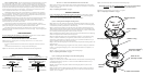
Step 6b: Use needle nose pliers to break off one of the three cable knockouts in the Mounting Flange,
as determined and marked in step 2 above. The choic of knockout must be determined in step 2.
(See illustration on page 2)
Step 7b: Position the cable in the gasket’s knife-slit while fitting the gasket into position in the
Mounting Flange.
Step 8: LOOSELY attach the Mounting Flange with Gasket to the surface, orienting it according to
the mark made in step 2. Use the supplied self-tapping screws or other stainless steel hardware (not
supplied). Do not overtighten.
FIGURE 1
Direct surface mounting for surfaces up to 1/4” thick Direct surface mounting for surfaces 1/4” – 1” thick
FIGURE 2
SRA-40 antenna
Mounting surface
6” SRA-40
cable
Extension
Shaft
SRA-40 antenna
Retaining nut
Lock washer
Cable to receiver
Retaining nut
Lock washer
Cable to receiver
Mounting surface
6” SRA-40 cable
Knife-slit for
passage of cable
Thread Adapter
Mounting
Gasket
6” cable and connector
Step 9: Attach the Thread Adapter with antenna to the Mounting Flange.
IMPORTANT: Rotate the cable counterclockwise while turning the Thread Adapter
clockwise. Make sure the cable turns freely and does not bind.
Step 10: Firm up the mounting screws, but do not over tighten.
Skip to “Completing the installation” on page 5.