


INTRODUCTION
Thank you for your purchase of the Rolls HM57 Headphone Monitor Interface.
This unit connects four mono 1/4” input signals and two main stereo mix signals to
either the HM58 or HM59 Headphone Monitor Remote. All signals are controlled
from the Remote units.
INSPECTION
1. Unpack and inspect the HM57 box and package.
If obvious physical damage is noticed, contact the carrier immediately to make a
damage claim. We suggest saving the shipping carton and packing materials for
safely transporting the unit in the future.
2. Please complete the Warranty Registration Card and return it to the factory.
SPECIFICATIONS
Connectors: 8: 1/4” jacks, DB25 connector, Pwr jack
Power Requirement
: 12 Volts AC
Dimensions: 5.625”W x 3.275”H x 1.325”D
Weight: 1 lb.
DESCRIPTION
BACK PANEL
MONO INPUTS: 4: 1/4” TRS balanced inputs for connection to a mixer auxiliary
outputs or equivalent.
MAIN INPUTS: 2: 1/4” TRS balanced inputs for connection to a mixer right and left
sub outputs or equivalent. The Left input is used for a mono source and will feed
both sides.
AUX INPUTS: 2 inputs to be used as stereo effects returns, or as a second pair of
stereo inputs. The Right input is used for a mono source and will feed both sides.
The Left input is a TRS jack that will accept a stereo input on the Tip and Ring.
FRONT PANEL
EXPANSION: 24 pin female OUTPUT jack.
PWR: LED indicating power is connected to the HM57.
12-17 VAC: Power jack - connect to the Rolls PS12.
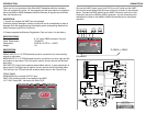
CONNECTION
Connect the HM57 power supply (the PS12) to an AC outlet and the HM57.
Connect the audio cables from the mixer to the unit as shown in the example
below. Connect the DB25 cable from the HM57 Expansion jack to the input
Expansion jack on the HM58 or HM59, whichever you are connecting your
headphone to. Refer to the HM58 or HM59 Owners Manual for their proper
operation.
AUXILIARY SENDS
MAIN
OUTPUTS
SUB
OUTPUTS
MAIN MIXER
1
2
3
4
R
L/MON
MAIN
INPUTS
R/MON L/ST
AUX
INPUTS
MONO
INPUTS
EXPANSION
PWR
12 - 17
VAC
+
-
HM57
HEADPHONE
MONITOR
INTERFACE
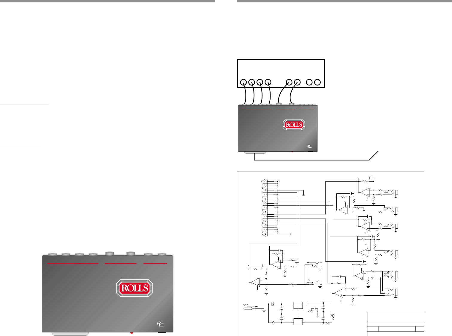
SCHEMATIC
1
2
3
4
R
L/MON
MAIN
INPUTS
R/MON L/ST
AUX
INPUTS
MONO
INPUTS
EXPANSION
PWR
12 - 17
VAC
+
-
HM57
HEADPHONE
MONITOR
INTERFACE
1
Rolls Corporation
5143 South Main Street
Salt Lake City, UT 84107
HM57.SCH
26-Oct-1999
Document Number:
Date: Sheet of
FXa
P O W E R
L E F T M A IN /
R IG H T M A IN
VDD
VCC
VCC
VDD
R 1 0 6
1 0 K
6
5
7
8
U 1 B
4 5 6 0
2
3
1
4
U 1 A
4 5 6 0
D 5
L D S G
C 1 1
2 2 0 0 U F
C 1 2
2 2 0 0 U F
1
14
2
15
3
16
4
17
5
18
6
19
7
20
8
21
9
22
10
23
11
24
12
25
13
J 1 0
D B 2 5
R 3
2 0 .0 K 1 %
R 4
2 0 .0 K 1 %
R 9
2 0 .0 K 1 %
R 8
2 0 .0 K 1 %
R 1
1 0 .0 K 1 %
R 2 1 0 .0 K 1 %
R 7
1 0 .0 K 1 %
R 6
1 0 .0 K 1 %
VCC
VDD
6
5
7
8
U 2 B
4 5 6 0
2
3
1
4
U 2 A
4 5 6 0
R 1 3
2 0 .0 K 1 %
R 1 4
2 0 .0 K 1 %
R 1 9
2 0 .0 K 1 %
R 1 8
2 0 .0 K 1 %
R 1 1
1 0 .0 K 1 %
R 1 2 1 0 .0 K 1 %
R 1 7
1 0 .0 K 1 %
R 1 6
1 0 .0 K 1 %
VCC
VDD
6
5
7
8
U 3 B
4 5 6 0
2
3
1
4
U 3 A
4 5 6 0
R 2 3
2 0 .0 K 1 %
R 2 4
2 0 .0 K 1 %
R 2 9
2 0 .0 K 1 %
R 3 2
2 0 .0 K 1 %
R 2 1
1 0 .0 K 1 %
R 2 2
1 0 .0 K 1 %
R 3 1
1 0 .0 K 1 %
R 3 0
1 0 .0 K 1 %
VCC
VDD
6
5
7
8
U 4 B
4 5 6 0
2
3
1
4
U 4 A
4 5 6 0
A U X 1
A U X 2
A U X 3
A U X 4
J 7
J 6
M O N O
M O N O
J 1
J 3
J 2
J 4
VCC
VDD
I
1
G
2
O
3
U 1 7
7 8 1 2
I
2
G
1
O
3
U 1 8
7 9 1 2
C 1 7
1 U
C 1 4
1 0 U
J 9
J 8
R 4 0 2 2 K
R 3 6 2 2 K
R 3 3
2 2 K
R 3 9
2 2 K
R 3 8
2 2 K
R 3 5
2 2 K
R 3 4
1 K
R 3 7
1 K
C 3 8
2 7 P F
C 3 9
2 7 P F
C 4 0
2 7 P F
C 4 1
2 7 P F
C 4 2
2 7 P F
C 4 3
2 7 P F
C 4 4
2 7 P F
C 4 7
2 7 P F
C
D
E
F
G
H
D 1
1 N 4 0 0 X
D 4
1 N 4 0 0 X
2
3
1
J 5
J A P D C
P H O N E 1 /4
P H O N E 1 /4
P H O N E 1 /4
P H O N E 1 /4
P C 1 /4
P C 1 /4
T IT L E : H E A D P H O N E M O N IT O R IN T E R F A C E H M 5 7
R E V
A
S IZ E
C 6 2
5 0 3
R R E T U R N /
P H O N E 1 /4
L R E T U R N /T R S
P H O N E 1 /4
1
To HM58 or HM59