


8
Rigging the Installation Line Array (continued)
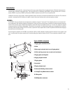
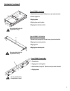
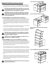
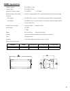
Pull-Back Bar
If using the pull-back bar, attach to the bottom enclosure at the bot-
tom-most splay angle adjustment holes at the rear of the rigging plate
by inserting the cap-head shoulder bolt through the mated pieces and
threading the lock nut (nylock) on the inside edge of the plates. Use a
5/8” (16 mm) shackle to attach to the pull-back bar shackle hole
located in the center of the main bar.
NOTE: All hardware/components must be rated for the
expected loads as determined by the Professional Engi-
neer responsible for suspension.
NOTE: A washer should not be used when attaching the
pull back bar. This will allow the pull back bar to pivot
freely.
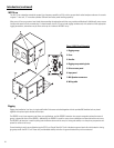
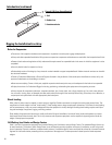
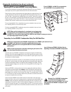
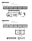
Extension Bar
The extension bar rigging plates can be moved, if required, by remov-
ing the two 7/8”mounting bolts, moving to the selected mounting
location, and reattaching. Tightening torque is to be 100 lb-ft of torque
(135.6 N-m) Ease-Focus software’s center-of-gravity calculator will
provide a suitable point (or two points) for desired down-tilt.
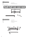
Attach the array frame to the extension bar rigging plates by centering
the array frame member between the extension bar rigging plates and
bolting together using the supplied 7/8” bolts.
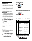
Attaching the WL115-sw to the Array Frame
All orientation of product is to be as viewed from the rear of the enclo-
sure. The QSC logo on the input plate will appear right side up when
the enclosure is oriented properly.
1- Attach the array frame to the suspension structure using 3/4" (20
mm) shackle and appropriate sling, cable, etc....
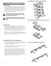
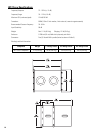
2- Refer to Figure 10. For all four rigging straps: Using an 6mm hex
wrench, remove the upper and lower rigging strap retaining bolts and
loosen the two bolts in between. Pull the inner and outer straps to
their outermost position; pull the center strap to its outermost posi-
tion, and align the retaining bolt holes with the threaded inserts of the
enclosure. Re-install the outermost rigging strap retaining bolts and
tighten all four bolts on each strap to 13 lb-ft (17.6 N-m).
Figure 8:PB2082-i under WL2082-i attached to FB2082-i.
Figure 9: Bolting order for EB2082-i Extension Bar rigging plates.
Figure 10: Extending the WL115-sw rigging straps.