


10
EN
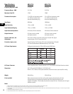
Specifications
MD-LP115 MD-LP118
Frequency Response, ±3dB 37-100 Hz 37-100 Hz
Frequency Range, -10dB 34-110 Hz 34-105 Hz
Maximum Peak SPL 127dB 128dB
Transducer Description 15-in. (381mm) long-throw woofer 18-in. (457mm) long-throw woofer
4-in. (102mm) voice coil with 4-in. (102mm) voice coil with
aluminum demodulating ring aluminum demodulating ring
Amp Power 800 Watts 800 Watts
Input Sensitivity 1.2V
rms
(+4dB) 1.2V
rms
(+4dB)
Input Headroom/Clipping 7.5V
rms
(+19.5dB) 7.5V
rms
(+19.5dB)
Input Connector/Impedance XLR female, 20k ohm balanced XLR female, 20k ohm balanced
Output Connector XLR male, wired in parallel XLR male, wired in parallel
with Input connector with Input connector
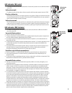
Controls, Indicators, and Gain control, 100 Hz Hi-cut filter switch, Clip/Limit (red LED), Signal
Adjustments presence (green LED), AC Power (blue LED)
Protection, Agency certs. Thermal limiting, On/Off muting, AC in-rush current limiting (<12A peak)
FCC class B (conducted and radiated emissions), UL/CE listed
AC Power Requirements Configured at the factory for 120V or 240V nominal, 50/60 Hertz
AC Power Connector Factory supplied cordset: Neutrik Powercon on 10’ (3m) #18AWG 120V North American cordset
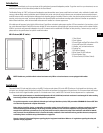
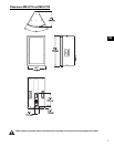
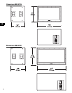
Dimensions 20.5” (521mm) W, 35.0” (889mm) H, 18.0” (457mm) D
Allow for 4.0” (100mm) of free space behind the enclosure to assure proper amplifier cooling
Weight 99 lb/44.9 kg 100 lb/45.4 kg
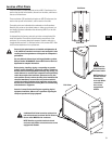
Finish and Grill Wear resistant textured paint finish with powder-coated perforated steel grill, black
colored enclosures are supplied with handles and white colored enclosures are not
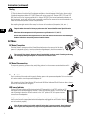
supplied with handles. 15 load-rated pick points that accept 3/8-inch, 16 threads per inch forged
shoulder eye bolts.
Notes:
1- Maximum Peak SPL: Calculated by adding the loudspeaker’s sensitivity (1W at 1m) to the peak power (dBw) of the amplifier provided.
2- Amplifier Power: The maximum sustained power at less than 1% clipping, averaged over the intended frequency range,
3- Input Sensitivity: The sine-wave input voltage required to reach amplifier clipping, measured within the frequency range used to determine Maximum Peak SPL, with the gain on “normal” and no gain reduction
due to limiting.
4- Input Headroom/Clipping: Maximum input voltage.
5- Input Connector/Impedance: RF shunt capacitance should not reduce impedance by more than 30% at 20k Hz.