


1999 Apr 22 3
Philips Semiconductors Product specification
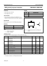
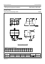
NPN general purpose transistors PMST6428; PMST6429
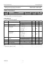
THERMAL CHARACTERISTICS
Note
1. Transistor mounted on an FR4 printed-circuit board.
CHARACTERISTICS
T
amb
≤ 25 °C unless otherwise specified.
Note
1. Pulse test: t
p
≤ 300 µs; δ≤0.02.
SYMBOL PARAMETER CONDITIONS VALUE UNIT
R
th j-a
thermal resistance from junction to ambient note 1 625 K/W
SYMBOL PARAMETER CONDITIONS MIN. MAX. UNIT
I
CBO
collector cut-off current I
E
= 0; V
CB
=30V − 10 nA
I
E
= 0; V
CB
=30V; T
j
= 150 °C − 10 µA
I
EBO
emitter cut-off current I
C
= 0; V
EB
=5V − 10 nA
h
FE
DC current gain V
CE
=5V
PMST6428 I
C
= 0.01 mA 250 −
I
C
= 0.1 mA 250 650
I
C
= 1 mA 250 −
I
C
= 10 mA 250 −
DC current gain V
CE
=5V
PMST6429 I
C
= 0.01 mA 500 −
I
C
= 0.1 mA 500 1250
I
C
= 1 mA 500 −
I
C
= 10 mA 500 −
V
CEsat
collector-emitter saturation
voltage
I
C
= 10 mA; I
B
= 0.5 mA; note 1 − 200 mV
I
C
= 100 mA; I
B
= 5 mA; note 1 − 600 mV
V
BE
base-emitter voltage I
C
= 1 mA; V
CE
= 5 V 560 660 mV
C
c
collector capacitance I
E
=i
e
= 0; V
CB
= 10 V; f = 1 MHz − 3pF
C
e
emitter capacitance I
C
=i
c
= 0; V
EB
= 0.5 V; f = 1 MHz − 12 pF
f
T
transition frequency I
C
= 1 mA; V
CE
= 5 V; f = 100 MHz 100 700 MHz