


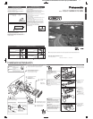
0 – 30°
53 mm
182 mm
4.5 mm – 6.0 mm
D
·
M
●
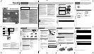
Please read these instructions carefully before using this product and keep this manual for future reference.
●
Bitte lesen Sie diese Bedienungsanleitung vor der Verwendung dieses Produktes aufmerksam durch und bewahren
Sie sie danach für spätere Nachschlagzwecke sorgfältig auf.
●
Prière de lire ces instructions attentivement avant d’utiliser le produit et garder ce manuel pour l’utilisation ultérieure.
YFM294C081CA PTW1206-1116 Printed in China
Matsushita Electric Industrial Co., Ltd.
Web Site : http://panasonic.net
Consult a professional for installation.
●Verify the radio using the antenna and speakers before installation.
Wenden Sie sich zum Einbau an einen Fachmann.
●Probieren Sie den Radiobetrieb vor dem Einbau mit Antenne
und Lautsprechern aus.
Prenez contact avec un spécialiste pour le montage.
●Vérifiez l’autoradio avant de procéder au montage.
●Mounting angle side to side : horizontal
front to rear : 0 – 30°
●Montagewinkel seitlich : horizontal
vorne-hinten : 0 – 30°
●Angle de montage latéral : horizontal
longitudinal : 0 – 30°
●Mounting space
●Einbauöffnung
●Espace nécessaire pour le montage
Before Installation/Vor dem Einbau/
Avant l’installation
Before Wiring/Vor der Verdrahtung/
Avant le câblage
How to install the unit/Einbau des Gerätes/Mode de montage de l’appareil
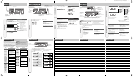
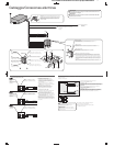
Supplied Hardware/
Mitgeliefertes Zubehör
/Matériel d’installation
1
1
1
1
2
No. Diagram
Q’ty
Item No. Diagram
Q’ty
Item
Mounting Collar
Einbauhalterung
Cadre de montage
Mounting Bolt (5 mm ø)
Befestigungsschraube (5 mm ø)
Boulon de fixation (5 mm ø)
Lock Cancel Plate
Verriegelungsfreigabeplatte
Plaque anti-blocage
Power Connector
Versorgungsstecker
Connecteur d’alimentation
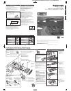
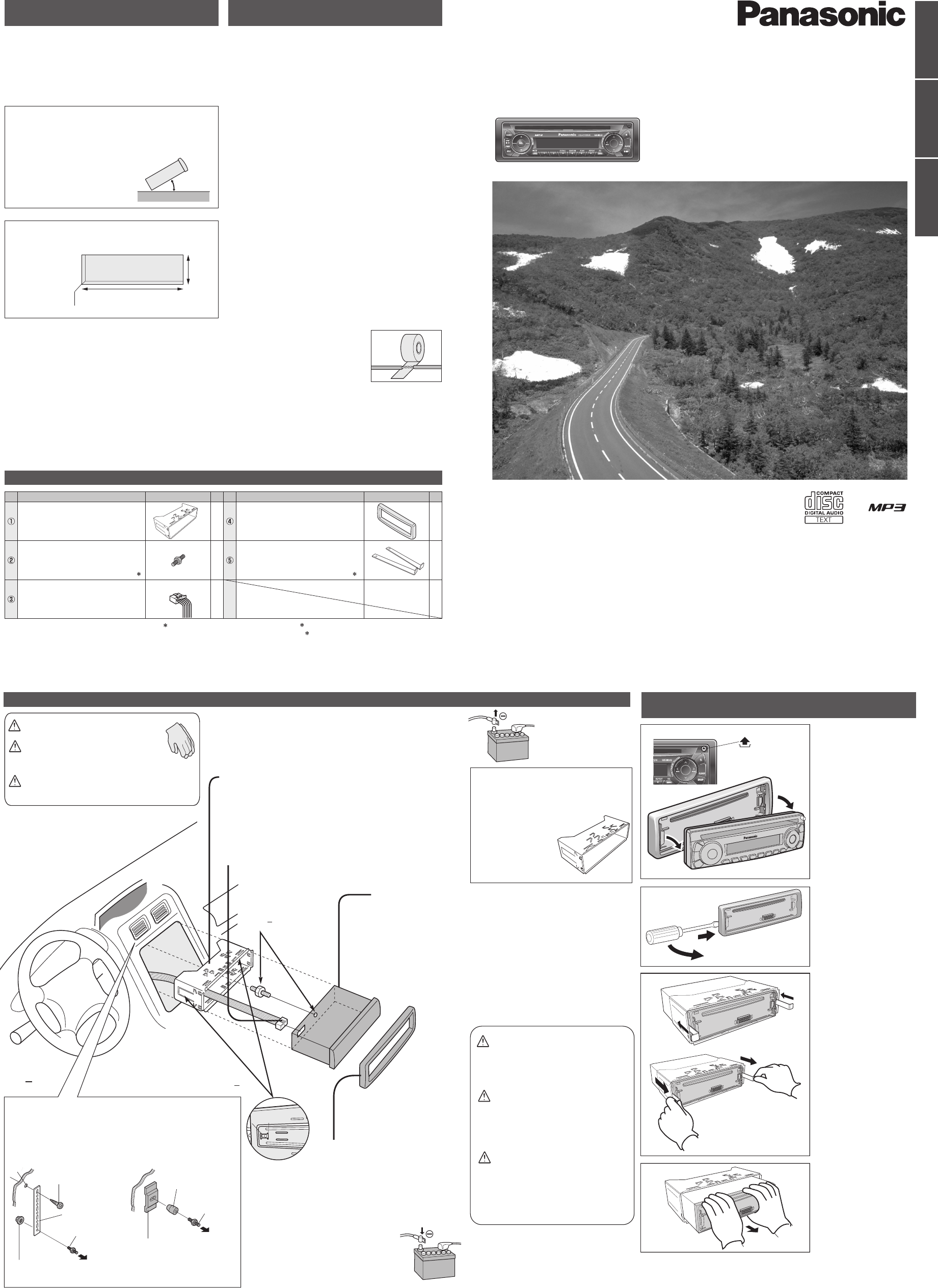
Installation/Einbau/Montage
Mounting collar q insertion
Bend mounting tabs.
Einsetzen der Einbauhalterung q
Biegen Sie die Einbaulaschen ab.
Insertion du cadre de montage
q
Replier les languettes de fixation.
Connection of power connector e
Anschluss des Versorgungssteckers
e
Raccordement du connecteur d’alimentation e
Tr im plate r mounting
Anbringen der Abdeckplatte r
Installation de la plaque de garniture
r
Battery cable reconnection
Wiederanschließen des Kabels
Rebranchement du câble
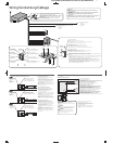
Remove the face plate.
Nehmen Sie das
Bedienteil ab.
Retirer le plaque de
façade.
1
Remove the trim plate r.
Entfernen Sie die
Abdeckplatte r.
Enlevez la plaque de
garniture r.
2
3
Pull out the unit with
both hands.
Ziehen Sie das Gerät mit
beiden Händen heraus.
Retirez l’appareil à deux
mains.
4
Tr im Plate
Abdeckplatte
Plaque de garniture
How to remove the unit/Ausbau des Gerätes/
Dépose de l’appareil
Caution
● Wear gloves for safety.
● Make sure that wiring is completed
before installation.
Vorsicht
● Tragen Sie Handschuhe, um
sich vor Verletzungen zu
schützen.
●
Achten Sie vor dem Einbau darauf,
dass die Verdrahtung fertiggestellt ist.
Attention ● Porter des gants à des fins de sécurité.
●
S’assurer que le câblage est terminé avant
l’installation.
Remove the cable from the battery negative terminal.
Trennen Sie das Kabel von der negativen Batterieklemme ab.
Retirer le câble de la borne négative de la batterie.
Bend appropriate tabs to secure the unit
without backlash.
Die entsprechenden Einbaulaschen so
umbiegen, dass das Gerät ohne Spielraum
fest sitzt.
Replier les languettes
de fixation appropriées
pour immobiliser
l’appareil sans
contrecoup.
q Screw the mounting bolt w into the main unit.
w Securing to the fire wall
e
Snap the right and left springs into each hole.
q Schrauben Sie die Befestigungsschraube w
in das Hauptgerät.
w An der Feuerschutzwand sichern
e
Lassen Sie die rechten und linken Federn in den
Löchern einschnappen.
q Visser le boulon de fixation w dans l’appareil
principal.
w Saisissage du pare-feu
e
Bouteroller les ressorts droit et gauche dans chaque trou.
Securing to the fire wall
Befestigung an Brandschutzwand
Obtenir un pare-feu
Using the rear support strap (Option)
Using the rubber bushing (Option)
Verwendung der Einbauleiste (Option) Verwendung der Gummibuchse (Option)
Utiliser de la barrette de support arrière (Option) Utiliser la bague d’amortisseur en caoutchouc (Option)
3 mm Tapping Screw (Option)
Blechschraube (Option)
Vis taraudeuse (Option)
To the unit
An das Gerät
Côté appareil
Rear Support Strap (Option)
Hinterer Stützstreifen
(Option)
Barrette d’appui arrière (Option)
Hexagonal nut (Option)
Sechskantmutter (Option)
Ecrou hexagonal (Option)
Rear Support Bracket
(supplied with car)
Einbauleiste (vorhanden im
Fahrzeug)
Support arrière
(fourni avec votre voiture)
Rubber Bushing (Option)
Gummibuchse (Option)
Bague en caoutchouc (Option)
To the unit
An das Gerät
Côté appareil
EnglishDeutschFrançais
Installation Instructions
Einbauanleitung
Instructions d’installation
Installation Instructions
Einbauanleitung
Instructions d’installation
Caution
When this unit is installed in dashboard,
ensure that there is sufficient air flow
around the unit to prevent damage from
overheating, do not block any ventilation
holes on the unit.
Vorsicht
Bei Einbau des Geräts im Armaturenbrett
sollte darauf geachtet werden, dass der
Luftstrom um das Gerät nicht behindert ist,
um Beschädigung durch Überhitzen zu
verhindern, und die Belüftungsöffnungen
des Geräts nicht blockiert sind.
Attention
Lorsque cet appareil est installé dans le
tableau de bord, assurez-vous qu’il y a une
circulation d’air suffisante autour de
l’appareil afin d’éviter tout endommagement
provoqué par une surchauffe et qu’aucun
trou d’aération de l’appareil n’est obturé.
FX0214C384ZB
YEAJ02874
w and t consist of a set. (ZZBISC1021N-J) w und t bestehen als Satz. (ZZBISC1021N-J)
w et t constituent un jeu. (ZZBISC1021N-J)
Remove Mounting Collar q and Trim Plate r from the main
unit temporarily, which are already mounted at shipment.
Die bei der Lieferung montierte Einbauhalterung q und
Abdeckplatte r vorübergehend vom Gerät abmontieren.
Démontez provisoirement le cadre de montage q et la
plaque de garniture r de l’appareil principal, qui sont déjà
mis en place lors de l’expédition.
YFC054C079YA
1
2
3
4
4
q
4
e
w
Snapping point
Einschnapppunkt
Position de rupture
Mounting Bolt w
Befestigungsschraube
w
Boulon de fixation w
Mounting Bolt w
Befestigungsschraube
w
Boulon de fixation w
Lock release
q Insert the lock cancel plate
t until you hear a click.
w Pull the main unit.
Verriegelungsfreigabe
q
Setzen Sie die
Verriegelungsfreigabeplatte
t
ein, bis Sie ein Klickgeräusch
vernehmen können.
w
Ziehen Sie an dem Hauptgerät.
Libération du verrouillage
q Introduisez la plaque anti-
blocage t jusqu’à entendre
un clic.
w
Dégager l’appareil principal
.
MP3 CD Player/Receiver
Model: CQ-C1325N/C1315N
(CQ-C1325N)
q
w
q
w
Exclusively operated with 12 V battery with negative (–) ground.
Connect the power lead (red) last.
(for non-ISO connector)
Connect the battery lead (yellow) to the positive (+) terminal of
the battery or fuse block terminal (BAT).
(for non-ISO connector)
Strip about 5 mm of the lead ends for connection.
(for non-ISO connector)
Apply insulating tape to bare leads.
Secure loosened leads.
Dieses Gerät ist ausschließlich für den Anschluss
an Bordnetze mit 12 V Batterie und negativer (–) Klemme
an Masse bestimmt.
Schließen Sie den Versorgungsleiter (rot) zum Schluss an
(wenn kein ISO-Stecker verwendet wird).
Schließen Sie das Batteriekabel (gelb) an die positive (+)
Klemme der Batterie oder an die (BAT) Klemme des
Sicherungsblocks an
(wenn kein ISO-Stecker verwendet wird).
Entfernen Sie etwa 5 mm der Isolierung von den Kabelenden
für den Anschluss
(wenn kein ISO-Stecker verwendet wird).
Isolieren Sie alle freiliegenden Leiter.
Sichern Sie alle losen Leiter.
Alimentez l’appareil absolument par la batterie de 12 V avec
sa polarité négative (–) mise à la masse.
Raccorder le fil d’alimentation (rouge) en dernier.
(pour un connecteur non-ISO)
Connectez le fil (jaune) à la borne positive (+) de la batterie ou
à la borne (BAT) de la boîte à fusibles.
(pour un connecteur non-ISO)
Dénudez les extrémités de fil de 5 mm environ pour la connexion
.
(pour un connecteur non-ISO)
Recouvrez les fils nus d’un ruban isolant.
Resserrez les connexions de fils.
Clank!
Fixation de l’appareil
principal
Befestigung des
Hauptgerätes
Main unit securing
5
6
4
w
e
q
CQ-C1325N/C1315N Installation Instructions (1-1) YFM294C081CA 2