


Disassembly Instruction:
If necessary, the unit may be removed from the panel and
opened.
Warning: Disconnect all ac power from the unit
before proceeding.
1. Make sure the AC power is disconnected.
2. Remove all wiring connections from the rear of the
meter. To remove power and input connectors bend the
side panel detents on the case outward to release the
connectors, then pull connectors from the meter.
3. To remove meter from the case, squeeze left and right
sides of the bezel to release, then pull from case.
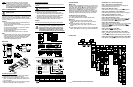
WIRING
Wire the instrument according to the figure shown below.
Warning: Do not connect ac power to your
device until you have completed all input and
output connections. This device must only be
installed by a specially trained electrician with
corresponding qualifications. Failure to follow
all instructions and warnings may result in injury!
Connect the main power connections as shown in the figure below.
FUSE Connector Output Type For 115Vac For 230Vac DC
FUSE 1 Output 1 Relay 3 A(T) 3 A(T) -
FUSE 2 Output 2 Relay 3 A(T) 3 A(T) -
FUSE 3 Power N/A 100 mA(T) 100 mA(T) 100 mA(T)
FUSE 4 Power N/A N/A N/A 400 mA(T)
Output 1 and 2 are for -AL Alarm Option only.
This Quick Start Reference provides information
on setting up your instrument for basic operation.
The latest complete Communication and Operational
Manual as well as free Software and ActiveX Controls
are available at www.omega.com/specs/iseries or on
the CD-ROM enclosed with your shipment.
SAFETY CONSIDERATION
This device is marked with the international
Caution symbol.
The instrument is a panel mount device protected in
accordance with Class II of EN61010-1. Remember that the
unit has no power-on switch. Building installation should
include a switch or circuit-breaker that must be compliant to
IEC 947-1 and 947-3.
SAFETY:
• Do not exceed voltage rating on the label located on
the top of the instrument housing.
• Always disconnect power before changing signal and
power connections.
• Do not use this instrument on a work bench without
its case for safety reasons.
• Do not operate this instrument in flammable or
explosive atmospheres.
• Do not expose this instrument to rain or moisture.
EMC:
• Whenever EMC is an issue, always use shielded cables.
• Never run signal and power wires in the same conduit.
• Use signal wire connections with twisted-pair cables.
• Install Ferrite Bead(s) on signal wire close to the
instrument if EMC problems persist.
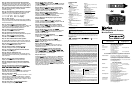
MOUNTING
Panel Mounting Instruction:
1. Using the dimensions from the panel cutout diagram
shown above, cut an opening in the panel.
2. Insert the unit into the opening from the front of the
panel, so the gasket seals between the bezel and the
front of the panel.
3. Slide the retainer over the rear of the case and tighten
against the backside of the mounting panel.
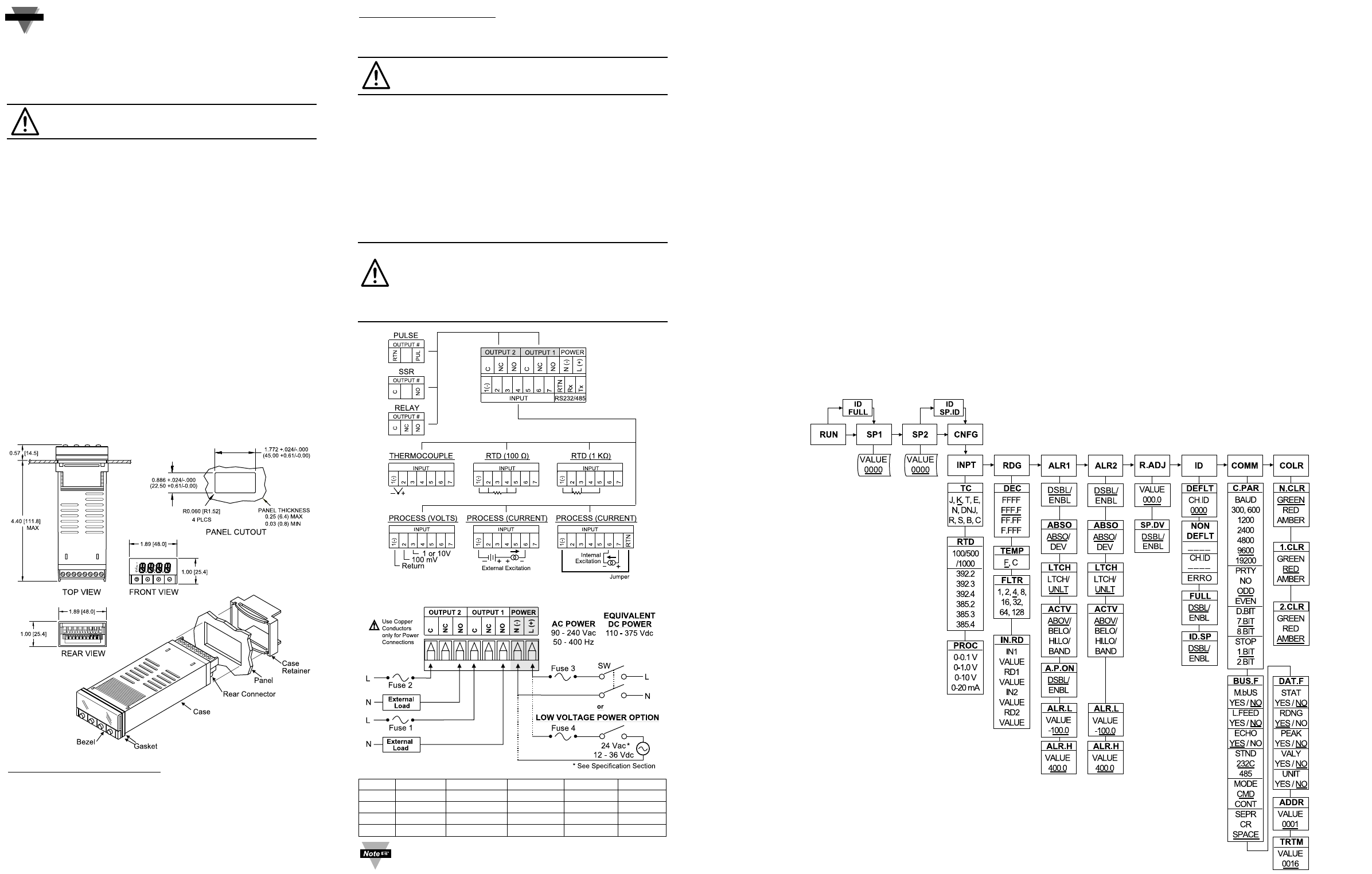
START HERE
FLOW CHART
CONFIGURATION
MENU Mode:
Flashing display in MENU Mode means you can make your
selection by pressing
b
button. If the flashing display is not
a four digit value, pressing
c
button will always direct the
instrument one step backward of the top menu item. The
second push on the
c
button will reset the instrument
except after the setpoint and the alarms, that will go to the
RUN Mode without resetting the instrument. The
a
button
will always sequence the instrument thru the menu items.
The
d
button has two functions:
1. To save a selected flashing display
2. To direct the instrument to the next submenu level
RUN Mode:
b
causes the display to flash the PEAK with the
corresponding value. Press again to go back to RUN
Mode.
c
causes the display to flash VALLEY with the
corresponding value. Press again to go back to RUN
Mode.
d
causes flashing PEAK or VALLEY to reset corresponding
values. Press
d
one more time to go back to RUN Mode.
_____ Underline denotes factory default setup
OPERATION - (For Thermocouple Input)
Step 1. Apply Power to the Instrument
When your device is first powered up it will display the
ambient temperature (assume 75°F).
Step 2. Enter Setpoint 1 Menu
Press
a
one time from run mode to get to
SP1
Setpoint 1.
Step 3. Enter the Setpoint 1 Value Submenu
Press
d
. Display shows the previous selection of Setpoint 1.
Step 4. Change the Setpoint 1 Value
Press
b
or
c
until desired value is displayed.
Step 5. Store the Setpoint 1 Value
Set the Setpoint 1 to 10 degree higher than Process value
(SP1 = 85) and press
d
to store, display flashes
STRD
message and advances to
SP2
Setpoint 2 Menu.
Step 6. Store the Setpoint 2 Value
Repeat steps 3 and 4. Set the Setpoint 2 to 5 degree higher
than Process value (SP2 = 80) and press
d
to store,
display flashes
STRD
message and advances to
CNFG
Configuration Menu.
Step 7. Enter the Input Type Menu
Press
d
to enter
INPT
Input Type Menu.
Step 8. Enter to the submenu items of Input Menu
Press
d
to display Input: Process, RTD or Thermocouple.
If flashing
T.ç
is displayed press
a
and proceed to Step 11.
Step 9. Scroll through available selection of Input Menu
Press
b
until a flashing
T.ç
for Thermocouple is displayed.