


52 Northtstar Explorer VHF Series: 710US, 710EU Operation and Installation Manual
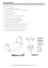
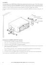
Checklist (middle picture opposite)
16. Two fl ush mount kit brackets
17. Two M5x32 screws
18. Two M5x10 screws
19. Two lock nuts
20. Two plastic bulkhead bushings.
21. Installation template (not pictured)
22. One 7 Amp spare fuse (not pictured) in case of accidental reverse of the battery polarity
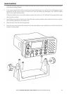
Installation Options
There are two ways to install the radio. You can choose:
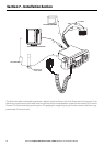
• a deck or overhead mounted gimbal installation. The reversible mounting gimbal is fi xed to to a suitable
site and the radio is placed into it. The radio can be removed for storage and the viewing angle can be
adjusted.
• a recessed installation. The radio is recessed into a cavity cut into a bulkhead. The radio fi xture is perma-
nent and the viewing angle cannot be adjusted.
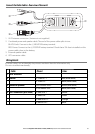
Location Requirements - Please check these before doing any cutting or drilling.
Whichever installation method you choose, ensure that the chosen location:
• is at least one metre (3') from the antenna
• allows easy connection to (at least) a 10 Amp fused 13.6V DC electrical source and the antenna
• is at least 45cms (1.5') from the compass to avoid creating magnetic deviation of the compass during
radio operation
• has a suitable space close by for installing the microphone bulkhead mount
• provides easy access to the front panel controls
• provides reasonable access to the wiring at the back of the radio
• provides enough room to fi x the DSC warning label (710US and 720US).