


Using the HPS Series with Tube-Type Amplifiers
Virtually all tube amplifiers must have a load connected at all
times. If the amplifier to be connected to the HPS-4/HPS-6 is a
tube amplifier, be sure to always have at least one pair of speak-
ers switched on at all times. An alternative is to permanently
connect a 150 ohm, 5 watt resistor across the tube amplifier’s
output in parallel with the HPS-4/HPS-6. See (Figure 1).
Installation
1. Select a convenient mounting location.
2. Run all the necessary. Label the wires for future reference.
See (Figure 2).
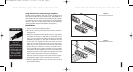
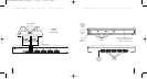
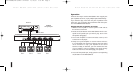
3. Make the connections to the speaker selector. The amplifi-
er/speaker connectors on the HPS are removable. If you
wish, you may remove the HPS’s connectors to facilitate
installation see (Figure 3). Strip 3/8" of insulation from the
end of each wire. Tightly twist the end of each wire until
there are no frayed ends. Insert each wire into the appro-
priate hole on the connector terminals. Be certain that
proper phasing is observed—connect the positive termi-
nals on the HPS to the positive terminals on the amplifier
and speakers and the negative terminals on the HPS to the
negative terminals on the amplifier and speakers. Re-install
the connectors if they were removed. See (Figure 4).
Insert the connector plug into the socket and lock in place-
by tightening captive screws on each side of connector.
4. Affix the appropriate label to the recessed area over each
on/off selector button.
5
H
IGH
P
OWER
S
PEAKER
S
ELECTION
S
YSTEM
“Tech Tip”
Wire size is
expressed by it’s
AWG (American Wire
Gauge) number. The
lower the AWG num-
ber, the larger the
wire, i.e., 12 AWG
wire is physically
larger than 14 AWG.
10
H
IGH
P
OWER
S
PEAKER
S
ELECTION
S
YSTEM
AMPLIFIER SPEAKER 4
Figure4
Installing the Connectors
AMPLIFIER
SPEAKER PAIRS
Figure3
Removing the Connectors
DS00358ACN/HPS-4/HPS-6 Printer 11/19/03 5:05 PM Page 5