


Final Installation in New
or Existing Construction
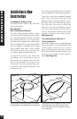
1. If it is possible to lay a batt of insulation
into the ceiling cavity do so. Remember
to use equal amounts of insulation for
each speaker.
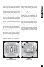
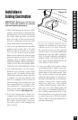
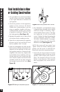
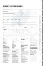
2. Check the position of the Impedance
jumper on the crossover PC board.
Choose the 4 ohm position if you are
using an amplifier capable of driving a
4 ohm load and you have only one pair
of speakers connected. Otherwise, use
the 8 ohm position
(See Figure 15).
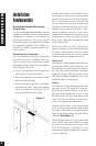
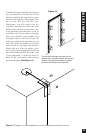
3. Separate the speaker wire so that at least
two inches of each conductor are free.
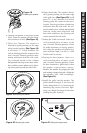
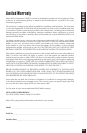
4. Open the no-strip terminal by applying
pressure to the red and black levers
until an audible “click” is heard.
5. Insert one unstripped wire fully into the
black and one into the red terminal. Pay
attention to the markings on the wire.
Each speaker must be connected to the
amplifier in the same way. Squeeze the
red and black levers until they click sig-
nifying that they have locked into the
wire. Check to make sure that the knife
assembly inside the no strip connector
has properly pierced the wire
(See
Figure 16)
.
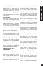
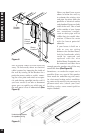
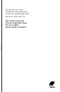
6. The DS6300AT and DS6500AT feature
a separate frame assembly which installs
with four clamps or mounting “dogs”
which hold the frame in place. The dogs
are tightened via four front-baffle
screws. Tighten the dogs by turning the
screws clockwise. DO NOT OVER-
TIGHTEN THESE SCREWS. Over-tight-
ening the clamps may make the grille
difficult to install.
(See Figure 17).
NOTE: The screws will turn easier if you
“prime” them first. Before installing each
speaker, turn the screws in and then turn
them back out to their original positions.
7. Insert the No-strip terminal into the
corresponding socket on the rear of the
speaker. Push it down until it locks in
place. The terminal will only fit in the
socket in one direction. If the terminal
does not properly seat, reverse the ter-
minal.
15
Final Installation in New or Existing Construction
Figure 17 Tightening the mounting “dogs”
Figure 16 No-Strip Speaker Wire Terminal.
Figure 15 Setting the Impedance jumper.