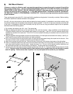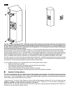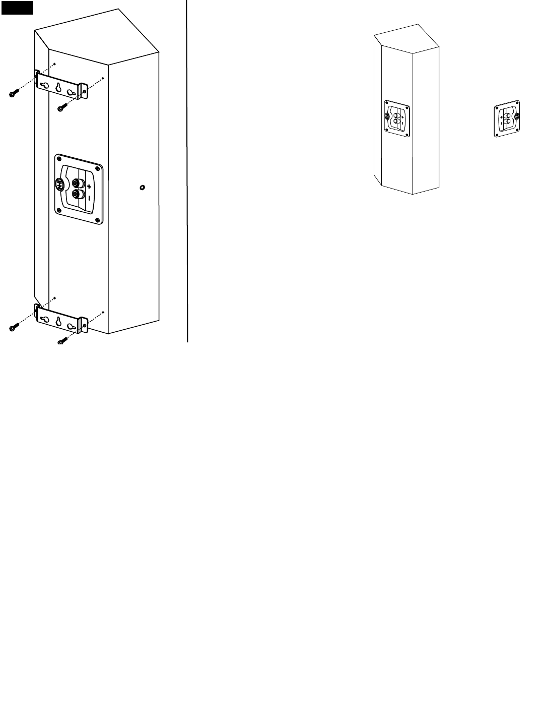
(see Fig. 7). When mounting the VS-1.4 vertically, use the middle keyhole on each bracket, and make sure that the brack-
ets are installed so that the narrow section of each keyhole faces the direction that will be “up” once the speaker is on
the wall. When mounting the VS-1.4 horizontally, use the appropriate “up”-facing keyhole on each bracket, making sure
that both brackets face the same direction.
8. Using the short screws, attach the brackets to the VS-1.4. Do not over-tighten the screws, as this may strip the pilot holes. On
power screwdrivers, use the low-torque setting. Tighten the screws enough so that the bracket cannot move on the speaker.
9. Attach speaker cable to the VS-1.4. When possible in new construction applications, run the cable inside the wall and have it
come out directly behind the location of the VS-1.4. If this is not possible, simply run the cable along the wall behind the VS-1.4.
Note: The speaker cable must be a maximum of 1/8-inches thick in order to fit between the speaker and the wall.
10. Hold up the VS-1.4 so that the brackets are aligned with the wall screws. Carefully place the brackets over the screws so that
the screw heads slide into the round sections of the keyholes. Slowly move the VS-1.4 downward until the bracket has locked
over the screw. Ensure that both brackets are securely mounted to their screws.
If you are unable to slide the VS-1.4 brackets down onto the wall screws, check to ensure:
• Nothing is obstructing the speaker
• The brackets are mounted on the speaker with both facing the same direction
• You are using the proper keyhole on both brackets
• The wall screws are exactly 16 inches apart, centered on the studs
• There is enough room between the screw head and the wall for the bracket to slide down.
!!
System Configurations
The VS-1.4 is optimized for use in the latest five-channel discrete digital surround systems. Since digital surround soundtracks
are mixed as five discrete channels, uniform tonality in the playback system is essential for achieving a believable “you are
there” sound. The VS-1.4 satellites and VT-1.4 towers utilize identical upper range drivers, so there are two system configurations
that will each provide matched timbre to all five channels:
1- Use a pair of VT-1.4 Audio / Video Towers for the front left and right speakers and three VS-1.4’s for the center and rear
speakers. Configure all low frequencies to be sent to the VT-1.4’s. Since the VT-1.4’s have built-in subwoofers, a
separate subwoofer is an option and not a necessity in this system.
2- Use five VS-1.4’s (front left, center and right, rear left and right) and a separate powered subwoofer (NHT SubOne, or
SubTwo) for the low frequency effects channel.
fig. 6


