


With the power switch in the off position and the power transformer plug not connected,
refer to the instructions and illustrations below.
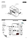
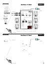
Locate the 10’ 9-pin to 9-pin
interface cable interface cable
interface cable interface cable
interface cable, plug one end of the 9-pin CM-7 interface connector to the subwoofer’s amplifier
located at the rear of the subwoofer unit and the other end to rear of the
CM-7 control moduleCM-7 control module
CM-7 control moduleCM-7 control module
CM-7 control module. If you have chosen to mount
the control module internal to a computer, than you must locate the 2’ 9-pin to 9-pin ribbon cable and refer to
illustration I-1illustration I-1
illustration I-1illustration I-1
illustration I-1.
Using the supplied
speaker cable speaker cable
speaker cable speaker cable
speaker cable connect the front left, front right, rear left, rear right and center satellite speakers to the
subwoofer amplifier’s
outputoutput
outputoutput
output. The connection terminals are simple plug-in type, needing only to be concerned with connecting
the output to the correspondent speaker and the type of connection. Refer to
illustration I-2illustration I-2
illustration I-2illustration I-2
illustration I-2.
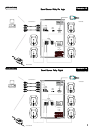
In the package please locate a 1.5’ dual RCA to stereo
3.5 mm stereo jack cable 3.5 mm stereo jack cable
3.5 mm stereo jack cable 3.5 mm stereo jack cable
3.5 mm stereo jack cable. This cable is intended to connect a
computer’s sound card, a portable CD player, or wherever a source with a 3.5mm jack is required to one of the amplifier’s RCA
inputs. If another type of connector is required, please check with your sound appliance vendor for the adaptor you may need.
Using this 1.5’ cable, simply plug the
RCARCA
RCARCA
RCA end into the
Audio Cable Audio Cable
Audio Cable Audio Cable
Audio Cable and connect the
RCA plugsRCA plugs
RCA plugsRCA plugs
RCA plugs into the amplifier’s
input input
input input
input.
The
red color RCA plug should be connected to the “right” input and the white color RCA to the “left” input. See to the specifica-
tions section for further details. Refer to
illustration I-2 to I-6 for your ”SPECIFICillustration I-2 to I-6 for your ”SPECIFIC
illustration I-2 to I-6 for your ”SPECIFICillustration I-2 to I-6 for your ”SPECIFIC
illustration I-2 to I-6 for your ”SPECIFIC
SOUND SOURCE CONNECTION.”SOUND SOURCE CONNECTION.”
SOUND SOURCE CONNECTION.”SOUND SOURCE CONNECTION.”
SOUND SOURCE CONNECTION.”
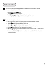
Power is supplied to the
S4 MidiLand™ 7100 S4 MidiLand™ 7100
S4 MidiLand™ 7100 S4 MidiLand™ 7100
S4 MidiLand™ 7100 via a supplied external
Power TransformerPower Transformer
Power TransformerPower Transformer
Power Transformer. The correct voltage adapter is
supplied for the territory you purchased the unit in. First, make sure to connect the coaxial power plug into the labeled power
receptacle on the rear of the subwoofer. Second, connect the country specific corded plug into an approved and properly function-
ing AC wall outlet.
DO NOTDO NOT
DO NOTDO NOT
DO NOT use an extension cord or an overly crowded wall plate. Third, make sure the power button is
pushed in on the control module.
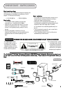
FEATURES
44
44
4
•
•
•
•
• 100 WATT RMS INTEGRATED POWER AMPLIFIER
• 6½” (165mm) SUBWOOFER
• 2½” (65mm) WIDEBAND SATELLITE SPEAKERS
• INTERNAL/EXTERNAL REMOTE CONTROL MODULE
• 5.1 MULTI-CHANNEL
• EXTERNAL LOW-NOISE POWER TRANSFORMER
l COMPLETE MAGNETIC/VIDEO SHIELDING
l SMALL DESKTOP “FOOTPRINT”
l DYNAMIC SOUND QUALITY
l PATENT PENDING CM-7 INTERFACE
l DOLBY DIGITAL READY
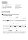
CONNECTIONS
3