


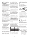
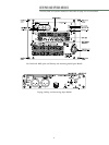

The rear panel of the USM-P has two
slots for processor modules. The top slot
contains the Audio Input and Control
Module; the bottom slot contains the
optional Remote Monitoring System™
(RMS) Module. A blank plate covers the
bottom slot if RMS is not installed. For
drawings of these modules, see page 11.
A
UDIO INPUT
There are three, interchangeable Audio
Input and Control Modules with opti-
mized connectors and controls for dif-
ferent applications. Each module has a
24V Fan connector to power an optional
fan (see page 11).
Each module uses a three-pin, female
XLR audio input connector with a 10kΩ
balanced input impedance wired with
the following convention:
Pin 1 -220 kΩ to chassis and earth
ground (ESD clamped)
Pin 2 -Signal
Pin 3 -Signal
Case -Earth (AC) ground and
chassis
Pins 2 and 3 carry the input as a differ-
ential signal. Use standard audio cables
with XLR connectors for balanced signal
sources. A single audio source can drive
multiple USM-Ps with a paralleled input
loop, creating an unbuffered hardwired
loop connection, with negligible loss in
signal level. For example, since the
input impedance of one USM-P is 10kΩ,
looping 20 USM-Ps produces a balanced
input impedance of 500Ω. With a 150Ω
audio source, the 500Ω load results in
only a 2.28dB loss.
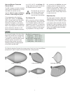
L
OOPING AUDIO INPUT MODULE
This standard module uses a balanced,
female XLR connector for audio input
and a male XLR loop connector to inter-
connect multiple speakers. The audio
input connector is hardwired with pin 2
hot to comply with audio industry stan-
dards. The loop connector, wired in par-
allel to the audio input, transmits the
input signal if the USM-P is turned off
for any reason.
LOOPING, POLARITY, AND ATTENUATING
AUDIO INPUT MODULE
This module has a balanced, female XLR
audio input connector, a male XLR loop
connector, an input polarity switch, and
a level attenuator knob. With the input
polarity switch in the up (+) position,
pin 2 is hot relative to pin 3, resulting
in a positive pressure wave when a posi-
tive signal is applied to pin 2. With the
switch down (-), pin 3 is hot relative to
pin 2, resulting in a negative pressure
wave when a positive signal is applied
to pin 2. The level attenuator knob
operates between 0 dB (no level attenu-
ation) in a fully clockwise position to -
12 dB in a fully counter-clockwise posi-
tion.
R
EMOTE MONITORING SYSTEM
The USM-P can be equipped to operate
with the Remote Monitoring System
(RMS) network and software application.
RMS displays signal and power levels,
driver and cooling fan status, limiter
activity, the state of the polarity switch,
attenuator level, and amplifier tempera-
ture for all speakers in the network on a
Windows-based PC. RMS is an excellent
field-diagnostic tool that removes the
guesswork from troubleshooting during
a performance. All Meyer RMS-compati-
ble speakers use the same RMS module
(depicted on page 11) so they can be
easily exchanged between speakers .
Installing an RMS module requires only
a Phillips screwdriver. Contact Meyer
Sound for more information about RMS.
6
THE MODULAR REAR PANEL
AMPLIFICATION, LIMITING, AND COOLING SYSTEM
A
MPLIFICATION AND LIMITING
Each driver in the USM-P is powered by
one channel of a proprietary Meyer
Sound amplifier utilizing complementary
power MOSFET output stages (class AB,
bridged, 350Wrms/ch). Each channel has
a limiter that prevents driver over-excur-
sion and regulates the temperature of
the voice coil. The limiters protect the
drivers without the glaring compression
effects imposed by typical limiters,
allowing high SPLs across each driver's
entire frequency range. Limiter activity
for the high and low channels is indicat-
ed by two yellow Limit LEDs on the rear
panel (the high limit is above the low
limit LED).
The USM-P performs within its acoustical
specifications and operates at a normal
temperature if the limit LEDs are on for
no longer than two seconds, and off for
at least one second. If either LED
remains on for longer than three sec-
onds, that channel incurs these negative
consequences:
• Increasing the input level will not
increase the volume.
• The system distorts due to clipping
and nonlinear driver operation.
While the USM-P limiters fully protect
the system under overload conditions
and exhibits smooth sonic characteris-
tics, we recommend that you do not
intentionally drive the USM-P into con-
tinuous limiting to attain compression
effects.
For applications where large amounts of
compression are required, we recommend
using an outboard compressor/limiter
for greater control of limit and compres-
sor effects.