


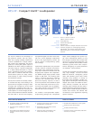

UPJ-1P specifications
architect specifications
meyer sound laboratories inc.
2832 San Pablo Avenue
Berkeley, CA 94702
T: +1 510 486.1166
F: +1 510 486.8356
techsupport@meyersound.com
www.meyersound.com
UPJ-1P - 04.134.097.01 B
Copyright © 2005
Meyer Sound Laboratories Inc.
All rights reserved
Operating Frequency Range
1
Frequency Response: Free Field
2
Phase Response
Maximum Peak SPL
3
Dynamic Range
Coverage
4
Low Frequency
High Frequency
6
Type
Maximum Common Mode Range
Connectors
Input Impedance
Wiring
DC Blocking
CMRR
RF Filter
TIM Filter
Nominal Input Sensitivity
Input Level
Type
Output Power
9
THD, IM, TIM
Load Capacity
Cooling
Connector
Voltage Selection
Safety Agency Rated Operating Range
Turn-on and Turn-off Points
10
Current Draw:
Idle Current
Max Long-Term Continuous Current (>10 sec)
Burst Current (<1 sec)
Ultimate Short-Term Peak Current Draw
Inrush Current
55 Hz - 20 kHz
66 Hz - 18 kHz ±4 dB
750 Hz - 18 kHz ±45°
128 dB
>110 dB
80° x 50°
2000 Hz
5
One 10" cone driver with neodymium magnet
Nominal impedance: 4 Ω
Voice coil size: 2"
Power-handling capability: 400 W (AES)
7
One 3" compression driver
Nominal impedance: 16 Ω
Voice coil size: 3"
Diaphragm size: 3"
Exit size: 0.75"
Power-handling capability: 100 W (AES)
7
Differential, electronically balanced
±15 V DC, clamped to earth for voltage transient protection
Female XLR input with male XLR loop output
10 kΩ differential between pins 2 and 3
Pin 1: Chassis/earth through 220 kΩ, 1000 pF, 15 V clamp network to
provide virtual ground lift at audio frequencies
Pin 2: Signal +
Pin 3: Signal - (optional polarity reversal switch)
8
Case: Earth ground and chassis
Differential DC blocking up to maximum common mode voltage
>50 dB, typically 80 dB (50 Hz – 500 Hz)
Common mode: 425 kHz; Differential mode: 142 kHz
<80 kHz, integral to signal processing
0 dBV (1 V rms, 1.4 V pk) continuous average is typically the onset of
limiting for noise and music
Audio source must be capable of producing a minimum of +20 dBV (10
V rms, 14 V pk) into 600 Ω to produce maximum peak SPL over the
operating bandwidth of the loudspeaker
Two-channel complementary MOSFET output stages (class AB/bridged)
300 W total
<.02%
4 Ω low channel, 16 Ω high channel
Forced air cooling over amplifier heatsink
PowerCon with looping output
Automatic
100 V AC - 240 V AC; 50/60 Hz
90 V AC to 264 V AC; 50/60 Hz
0.41 A rms (115 V AC); 0.33 A rms (230 V AC); 0.42 A rms (100 V AC)
3.2 A rms (115 V AC); 1.6 A rms (230 V AC); 3.7 A rms (100 V AC)
5 A rms (115 V AC); 2.5 A rms (230 V AC); 5.8 A rms (100 V AC)
17 A pk (115 V AC); 8.5 A pk (230 V AC); 20 A pk (100 V AC)
15 A pk (115 V AC); 13 A pk (230 V AC); 15 A pk (100 V AC)
Equipped for two-conductor twisted-pair network, reporting all
amplifier operating parameters to system operator’s host computer.
Acoustical
Coverage
Crossover
Transducers
Audio Input
Amplifiers
AC Power
RMS Network (Optional)
The loudspeaker shall be a self-powered, full-range
system. The transducers shall consist of a 10-inch diameter
cone driver and a 3-inch diaphragm compression driver on
a 80° x 50° horn. The horn shall allow rotation to provide
the wider coverage pattern in either the horizontal or
vertical plane relative to the cabinet’s vertical axis.
The loudspeaker system shall incorporate internal
processing electronics and a two-channel amplifier.
Processing functions shall include equalization, phase
correction, signal division, and driver protection for
the high- and low-frequency sections. The acoustical
crossover point shall be 2 kHz. Each amplifier channel
shall be class AB/bridged with complementary MOSFET
output stages. Burst capability shall be 300 watts total into
a nominal load of 4-ohms low channel and 16-ohms high
channel. Distortion (THD, IM, TIM) shall not exceed 0.02%.
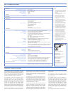
Performance specifications for a typical production unit
shall be as follows, measured at 1/3 octave resolution:
Notes:
Operating frequency range shall be 55 Hz to 20 kHz. Phase
response shall be ±45° from 750 Hz to 18 kHz. Maximum
SPL shall be 128 dB at 1 meter. Coverage (-6 dB points)
shall be 80° x 50°, horizontal or vertical dependent on
horn orientation.
The audio input shall be electronically balanced with a
10 kΩ impedance and accept a nominal 0 dBV (1 V rms, 1.4
V pk) input signal. Connectors shall be XLR (A-3) type with
male input and female loop-through output. RF filtering
shall be provided, and CMRR shall be greater than 50 dB
and typically 80 dB (50 Hz – 500 Hz).
The internal power supply shall perform automatic voltage
selection, EMI filtering, soft current turn-on and surge
suppression. Powering requirements shall be nominal
100 V, 115 V or 230 V AC line current at 50 Hz or 60 Hz
frequency. Current draw during burst (<1 sec) shall be
5 A at 115 V, 2.5 A at 230 V and 5.8 A at 100 V. Current
inrush during soft turn-on shall not exceed 15 A at 115 V.
AC power connector shall be a locking connector with
looping output.
The loudspeaker system shall provide facilities
for installing Meyer Sound’s optional RMS remote
monitoring system.
All loudspeaker components shall be mounted in an
acoustically vented trapezoidal enclosure constructed
of premium birch plywood with a hard black textured
finish. The front protective grille shall be powder-
coated hex-stamped steel. Dimensions shall be 11.15"
wide x 22.43" high x 12.25" deep (283 mm x 570 mm
x 286 mm). Weight shall be 46 lbs (20.87 kg). Integral
high-strength, 6061-T6 aluminum top plates with
threaded M8 metric holes shall accommodate Meyer
Sound proprietary rigging hardware and third-party
accessories.
The loudspeaker shall be the Meyer Sound UPJ-1P.
1. Recommended maximum operating
frequency range. Response depends
upon loading conditions and room
acoustics.
2. Measured with 1/3 octave frequency
resolution at 4 meters.
3. Measured with music at 1 meter.
4. The UPJ horn can be rotated to
provide an 80° x 50° coverage
pattern in either the horizontal or
vertical plane.
5. At this frequency, the transducers
produce equal sound pressure levels.
6. The driver is coupled to an 80° x 50°
constant-directivity horn.
7. Power handling is measured under
AES standard conditions: transducer
driven continuously for two hours
with band-limited noise signal
having a 6 dB peak-average ratio.
8. Two additional input module options
are available with polarity reversal
switch and an attenuator (0 dB to
-18 dB): one looping and one with
two inputs for mono summing.
9. Amplifier wattage rating based
on the maximum unclipped burst
sine-wave rms voltage the amplifier
will produce into the nominal load
impedance. Low and high channels
30 V rms (42 V pk).
10. No automatic turn-off voltages.
Voltages above 265 V AC are fuse
protected but may cause permanent
damage to the power supply.
Voltages below 90 V AC may result in
intermittent operation.
EuropeanOffice:
MeyerSoundLab.GmbH
CarlZeissStrasse13
56751Polch,Germany
MadebyMeyerSoundLaboratories
Berkeley,California USA
o
f
N
o
r
t
h
A
m
e
r
i
c
a
,
I
n
c
.
C
US
T
U
V
R
h
e
i
n
l
a
n
d