


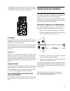

#
Use the table below as a guide to select cables and circuit
breakers with appropriate ratings for your operating voltage.
UPA-P Current Ratings
V511V032V001
SMReldIA52.0
SMR
A31.0
SMR
A3.0
SMR
SMRsuounitnoC.xaMA8.2
SMR
A4.1
SMR
A2.3
SMR
SMRtsruB.xaMA2.3
SMR
A6.1
SMR
A7.3
SMR
tsruBgniruDkaeP.xaMA0.5
SMR
A5.2
SMR
A8.5
SMR
To determine the minimum total service power required
by a system of UPA-P, or other Meyer self-powered speak-
ers, add their maximum continuous RMS currents to-
gether. We recommend allowing an additional 30% above
the minimum amperage to prevent peak voltage drops at
the service entry and nuisance tripping.
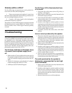
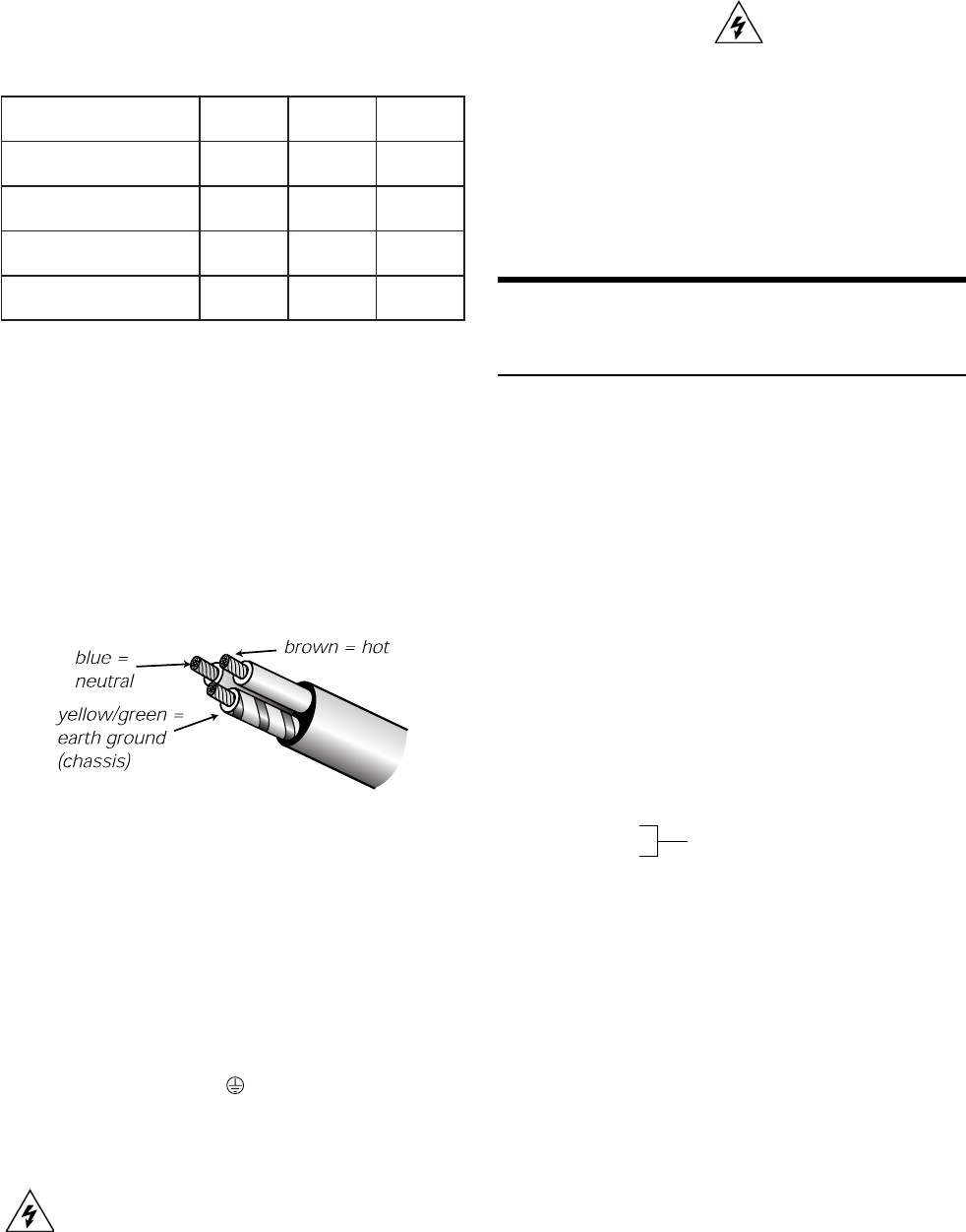
Power Connector Wiring
Use the following AC cable wiring diagram to create
international or special-purpose power connectors:
AC cable color code
If the colors referred to in the diagram don't correspond to
the terminals in your plug, use the following guidelines:
• Connect the blue wire to the terminal marked with
an N or colored black.
• Connect the brown wire to the terminal marked
with an L or colored red.
• Connect the green and yellow wire to the terminal
marked with an E (or ) or colored green (or green
and yellow).
Safety Issues
Do not use a ground-lifting adapter or cut the AC
cable ground pin.
Keep all liquids away from the UPA-P to avoid hazards
from electrical shock.
Do not operate the unit with worn or frayed cables;
replace them immediately.
If the UPA-P will be installed outdoors contact Meyer
Sound for information about the rain hood and weather
protection for the drivers and electronics
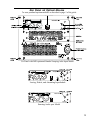
The Modular Rear Panel
The rear panel of the UPA-P has two slots for processor
modules. The top slot contains the Audio Input and
Control Module; the bottom slot contains the optional
Remote Monitoring System™ (RMS) Module. A blank
plate covers the bottom slot if RMS is not installed. For
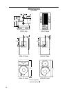
drawings of the modules refer to page 13.
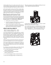
Audio Input
There are three, interchangeable Audio Input and Control
Modules with optimized connectors and controls for dif-
ferent applications. Each module has a 24V Fan connec-
tor to power an optional fan (see page 7).
Each module uses a three-pin, female XLR audio input
connector with a 10 kΩ balanced input impedance wired
with the following convention:
Pin 1 — 220 kΩ to chassis and earth ground (ESD clamped)
Pin 2 — Signal
Pin 3 — Signal
Case — Earth (AC) ground and chassis
Pins 2 and 3 carry the input as a differential signal. Use
standard audio cables with XLR connectors for balanced
signal sources. A single audio source can drive multiple
UPA-Ps with a paralleled input loop, creating an unbuf-
fered hardwired loop connection, with negligible loss in
signal level. For example, since the input impedance of
one UPA-P is 10 kΩ, looping 20 UPA-Ps produces a bal-
anced input impedance of 500Ω. With a 150Ω audio source,
the 500Ω load results in only a 2.28 dB loss.
Differential Inputs