


S-1
Control
Electronics
Unit
Operating Instructions
Meyer Sound Laboratories, Inc.
2832 San Pablo Avenue
Berkeley, CA 94702
Limiter Operation
To verify limiter operation in the field:
• Disconnect loudspeakers, leaving the amplifier and
the S-1 in their standard connection configuration.
• If your amplifier requires a load, use resistive loads
sufficient to dissipate the full power of the amplifier.
• Turn on both the S-1 and the amplifier.
• Set the VHF switch to VAR, the Lo Cut out, and the
Safe switch in.
• Supply an input to the S-1, preferably a sine-wave
oscillator. If you do not have an oscillator, use a
microphone and a mixer to produce a line level signal.
Set the input frequency according to this table:
Oscillator Microphone
LF limiter 200 Hz low growl
HF limiter 5,000 Hz loud whistle
VHF limiter 16,000 Hz loud hiss
• Bring up the input until you see the corresponding
limit indicator come on. Since the indicator will light
only if the limiter actually operates, it provides a
positive indication that the limiter is functioning.
Balancing
Amplifier Gain
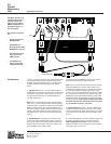
The standard connection configuration for the S-1 Control
Electronics Unit uses a single two-channel amplifier as a
biamplifier, one channel for the lows and one for the
highs. In large systems where a number of S-1’s are
used, some may prefer to assign one or more amplifiers
only to the lows, and other amplifiers only to the highs. In
either case, the Lo and Hi amplifiers must have equal
voltage gain. If they do not, you may balance your sys-
tem using an oscillator and an RMS-reading voltmeter.
• Connect the S-1 and amplifiers as you wish to use
them, leaving speakers disconnected.
• If an amplifier requires a load, use an 8-ohm resistor
sufficient to dissipate the full power of the amplifier.
• Input the oscillator to the S-1 and set its frequency to
1400 Hz ±5 Hz (Use a frequency counter if possible).
• Set the S-1 Lo Cut switch out, the VHF switch to
CAL, and the Safe switch out.
• Measuring with the voltmeter at the Hi amplifier out-
put, advance the S-1 Attn dB control to a convenient
reading (a few volts).
• Now measure at the Lo amplifier output, If the level is
different, adjust the input level control of the amplifier
whose output voltage is higher until the Hi and Lo
outputs are equal.