S-1
Control
Electronics
Unit
Operating Instructions
Meyer Sound Laboratories, Inc.
2832 San Pablo Avenue
Berkeley, CA 94702
The Meyer Sound S-1 is
a single-channel active
signal processor de-
signed for use with the
USM-1 Loudspeaker. It
occupies a single 1
3
⁄4-
inch rack space.
The functions of the S-1
are:
• Active crossover for
biamplification
• SpeakerSense™
driver protection with
MultiSense™ function
• True excursion limit-
ing to protect the
USM-1 drivers
• Loudspeaker fre-
quency and phase
response alignment
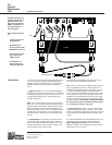
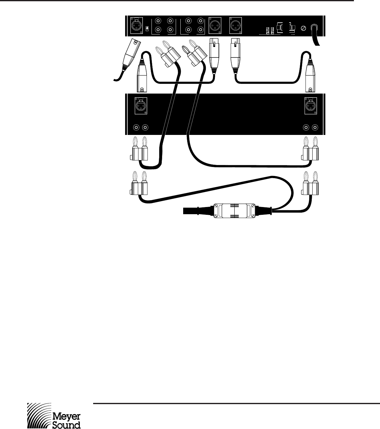
Connections
The S-1 operates at line level and is intended to be the
final component in the signal chain before the power
amplifier. Connections between the S-1 and the power
amplifier should be made according to the diagram
above.
1. Signal inputs to the S-1 may be either balanced or
unbalanced. For best signal-to-noise ratio, use balanced
connections operating at +4 dBu nominal. The S-1 will
accept peak input levels up to +26 dBu balanced, or
+20 dBu unbalanced.
Note: The S-1 utilizes Meyer Sound’s exclusive ISO™
Input. Pins 1, 2 and 3 are transformer-isolated, and the
connector shell is connected to earth ground. The Input
GND/ Lift switch controls the connection between pin 1
and circuit common, which is tied to AC/chassis ground
through a 500 ohm resistance. If hum problems occur,
this switch may be used to control ground loops in the
system.
2. SpeakerSense™ connections are made from the
output of the power amplifier back to the S-1 Sense in-
puts. The Hi output of the power amplifier must be con-
nected to the Hi Sense input, and the Lo output of the
power amplifier to the Lo Sense input .
The Sense connection must be made in order for the
driver protection circuitry to operate properly.
Note: The S-1 Sense inputs incorporate Meyer Sound’s
exclusive MultiSense™ function, which allows use of
multiple power amplifiers driven in parallel from a single
S-1 and having different voltage gains and/or power
ratings. The S-1 accommodates up to two power amplifi-
ers, and provides a separate Sense input for each. The
MultiSense circuit automatically tracks the power ampli-
fier with the greatest output swing to control the system
protection circuitry. These inputs are polarity-sensitive:
be certain that they are connected with correct polar-
ity, as indicated on the S-1 rear panel.
3. Signal outputs from the S-1 are active balanced at
+4 dBu nominal operating level, with pin 1 tied to earth/
chassis ground through a 500 ohm resistance. The maxi-
mum output level is +26 dBu balanced (+20 dBu unbal-
anced).
4. Connections between the power amplifier output and
the USM-1 should be made in accordance with the
USM-1 Operating Instructions. These connections
must be verified for correct polarity and correct channel
assignment (Hi to Hi, Lo to Lo).
PUSH
+–
PUSH
Input
Lift
GND
Input
Hi Sense
Lo Out
Hi Out
1/4 A SloBlo
90-105
105-125
210-250
180-210
AC Voltage
+
-
+
-
+
-
+
-
90-250 VAC
50-60 Hz
100mA MAX
CAUTION:
Set voltage before applying power.
AC Voltage Ranges
210 - 250
180 - 210
105 - 125
90 - 105
Lo Sense
Hi Channel
PUSH
+–
Lo Channel
Amplifier
Loudspeaker Cable
Input