


Operating Instructions
Meyer Sound Laboratories, Inc.
2832 San Pablo Avenue
Berkeley, CA 94702
MPS-3
Control
Electronics
Unit
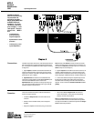
Output Level
Controls and
Mono Switch
The Output Level Controls regulate the gain of each
channel of the MPS-3. Their range is from off to 0 dB,
with -6 dB gain at the center position.
When the Mono Switch is engaged (in), the two input
channels are summed and routed to both outputs. While
operating in mono, each output's level is still controlled by
its respective Level Control. When the Mono Switch is
disengaged (out), the MPS-3 operates in stereo.
Lo Cut Switch
The Lo Cut switch on the MPS-3 front panel introduces a
6 dB/octave high pass filter at 160 Hz on both channels.
This filter is designed to reduce any low frequency empha-
sis caused by corner placement of the MPS-305 or MPS-
SpeakerSense™
Driver Protection
Through the Sense connections between the MPS-3 and
the power amplifier, the SpeakerSense circuitry of the
MPS-3 continuously monitors the voltages across the
loudspeaker drivers. If the amplifier ouput exceeds the
safe operating limits of the drivers, either an RMS limiter
or a Peak limiter will be automatically activated, holding
down the power level of the MPS-3 output.
The operation of the SpeakerSense circuitry is indicated
by a single, bi-colored Sense/Limit indicator LED for each
channel .
The function of the Sense/Limit indicator is as follows:
• Signal Presence Indicator. The Sense/Limit indica-
tor lights green to indicate signal presence, and veri-
fies that the Sense connections between the amplifier
and the MPS-3 are made. The indicator will flicker
green at low signal levels.
• Limit Indicator. The Sense/Limit indicator lights red
whenever the limiter is activated. A moderate amount
of red flickering of this indicator is acceptable. The
RMS limiter has an attack time of 60 msec, and is
designed to protect the system in sustained high level
use.
Limiter Operation
To verify limiter operation in the field:
• Disconnect loudspeakers, leaving the amplifier and the
MPS-3 in their standard connection configuration.
• If your amplifier requires a load, use resistive loads
sufficient to dissipate the full power of the amplifier.
• Turn on both the MPS-3 and the amplifier.
• Switch the Lo Cut out.
• Supply an input to the MPS-3, preferably a sinewave
oscillator. If you do not have an oscillator, use a
microphone and a mixer to produce a line-level signal.
• Set the input frequency of the oscillator to 1 kHz, or
whistle into the microphone.
• Bring up the Output Level until you see the Sense/
Limit indicator light red. Since the indicator will light
red only if the limiter actually operates, it provides a
positive indication that the limiter is functioning.
AC Voltage
Selector and
Fuse
Primary protection for the MPS-3 is provided by a
1
¦4 A
SloBlo fuse located in a receptacle adjacent to the AC
cord. Before examining or replacing the fuse, first unplug
the AC power cord. To replace the fuse, insert a flat-
blade screwdriver in the fuse cap and gently turn counter-
clockwise. The fuse will spring from its socket. Replace
only with a fuse of the type and rating specified by Meyer
Sound.
The MPS-3 must have the correct voltage setting and fuse
for the AC power source in your area. To change the AC
voltage setting, first unplug the AC power cord. Using a
small flat-blade screwdriver, move the slide switch to the
appropriate position as indicated by the adjacent panel
legend.
355 loudspeakers, but can also be used to compensate
for the proximity effect of cardioid microphones. The Lo
Cut switch is also useful for preventing speaker overload
when using MPS-305 loudspeakers.