


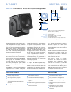

MM-4 specifications
1. TorealizetheMM-4’sfull
capabilities,anMM-4CEUmust
beused.Theamplifierdrivingthe
loudspeakersshouldbecapable
of49voltsRMSattheratedload
impedance,andprovideavoltage
gainbetween10and30dB(20
dBforoptimalS/Nratioand
protection).Thepowerratingof
theamplifiershouldbeasfollows:
1MM-4/ch(16Ω)150W
2MM-4/ch(8Ω)300W
4MM-4/ch(4Ω)600W
8MM-4/ch(2Ω)1200W
2. Recommendedmaximumoperating
frequencyrange.Response
dependsonloadingconditionsand
roomacoustics.
3. Freefield,measuredwithone-
thirdoctavefrequencyresolution
at4meters.
4. Measuredwithpinknoiseat1
meter.
5. Measuredat1meter,driven
continuouslyfortwohourswith
pinknoisesignalhavinga12.5dB
peak-averageratio.
6. Powerhandlingismeasured
underAESstandardconditions:
transducerdrivencontinuously
fortwohourswithband-limited
noisesignalhavinga6dBpeak-
averageratio.Aluminumenclosure
dissipatesheatgeneratedby
driver.
7. Whenusingmultiplesenselines,
alllinesmustbeinsameelectrical
polarity.
architect specifications
Copyright © 2007
Meyer Sound Laboratories Inc.
All rights reserved
meyer sound laboratories inc.
2832 San Pablo Avenue
Berkeley, CA 94702
T: +1 510 486.1166
F: +1 510 486.8356
info@meyersound.com
www.meyersound.com
MM-4 - 04.091.033.01 C
EuropeanOffice:
MeyerSoundLab.GmbH
CarlZeissStrasse13
56751Polch,Germany
MadebyMeyerSoundLaboratories
Berkeley,CaliforniaUSA
Operating Frequency Range
2
Frequency Response
3
Phase Response
Maximum Peak SPL
4
Maximum Continuous SPL
5
Horizontal
Vertical
Type
Maximum Common Mode Range
Connector(s)
Input Impedance
Wiring
DC Blocking
CMRR
RF Filter
Input Level
Type
Out Voltage
Connectors
Output Impedance
Wiring
Hum and Noise
Dynamic Range
THD
Response Accuracy
Connector
Voltage Selection
UL/CE Rated Voltage
Current Draw
LED Indicators
Controls
SpeakerSense Connectors
7
Physical Dimensions
Weight
Finish
120 Hz - 18 kHz
160 Hz - 16 kHz ±4 dB
700 Hz - 17 kHz ±45°
112.5 dB
100 dB
80° (3 kHz - 14 kHz ±10°); 120° (below 2 kHz)
80° (3 kHz - 14 kHz ±10°); 120° (below 2 kHz)
One 4" cone driver
Nominal impedance: 16 Ω
Voice coil size: 0.75"
Power-handling capability: 100 W (AES)
6
Differential, electronically balanced; RF and transient protected
±15 V DC, clamped to earth for voltage transient protection
Two female XLR, one for each input channel
10 kΩ differential between pins 2 and 3
Pin 1: Chassis/earth through 11 kΩ, 1000 pF, 15 V clamp network to
provide virtual ground lift at audiofrequencies; Pin 2: Signal +;
Pin 3: Signal -; Case: Earth ground and chassis
None
>60 dB, typically 80 dB (50 Hz - 1 kHz)
Common mode 850 kHz; differential mode 370 kHz
Maximum input voltage 25 V peak-peak (+21 dBu sine wave)
Active push-pull, electronically balanced, capable of driving
600 Ω load; RF and transient protected
Maximum 50 V peak-peak (+27 dBu sine wave)
Two male XLR, one for each output channel
200 Ω differential between pins 2 and 3
Pin 1: Chassis/earth; Pin 2: Signal +; Pin 3: Signal -
<-90 dBV (A-weighted)
>115 dB
<0.01%, typically <.002%
<0.25 dB (20-20 kHz)
IEC 320
Switch selectable on rear panel
90 - 130 V AC; 180 -260 V AC; 50/60 Hz
0.160 A max (rear panel T 160 mA fuse protected)
Sense Threshold/Gain Detect: (2) Red/Green LEDs, one per channel;
RMS Limiters: (2) Yellow LEDs, one per channel; Peak Limiters:
(2) Yellow LEDs, one per channel; Power: (1) Green LED
Front panel: (2) Rotary input attenuators, one per channel;
(2) Recessed low cut filter switches, one per channel;
(1) AC power latching push switch
Rear Panel: (1) AC voltage selector, recessed; (1) T250V fuse and holder
MultiSense, (4) dual banana, two per channel
19.00" w x 1.75" h x 7.75" d standard rack mount (482 mm x 44 mm x 197 mm)
8 lbs, 4 oz (3.74 kg)
Black, powder coated
Acoustical
(MM-4CEU required)
1
Coverage
Transducer
Audio Input
Audio Output
Audio Performance
AC Power
Physical
The loudspeaker system shall consist of a single 4-inch (102
mm) diameter cone transducer with a 100 watt (AES), 16-ohm,
long-excursion voice coil with air-cooled ceramic magnet
structure and mounted in a sealed aluminum enclosure that
provides heat sinking for the transducer’s voice coil. The
aluminum enclosure shall have exterior dimensions of 40-inch
(102 mm) wide by 4-inch (102 mm) high by 4.2-inch (107 mm)
deep (including the grille but excluding the connector) and it
shall weigh 3 lbs 14 oz (1.76 kg). The loudspeaker system shall
produce continuous SPL of 100 dB at 1 meter with peak output
of 112.5 dB at 1 meter from 160 Hz to 16 kHz when used with
the required Meyer Sound MM-4CEU control electronics unit
and a third-party audio power amplifier. The power amplifier
shall be a professional grade, direct drive (transformerless
output) power amplifier determined to be capable of stable
long term output of 49 volts rms (70 volts peak) at the rated
load impedance. The loudspeaker system shall be weather
resistant and suitable for sheltered outdoor applications by
Notes:
virtue of an aluminum enclosure, special sealants, watertight
connector and chemically treated transducer cone. The
loudspeaker enclosure shall be fitted with a 3/8-inch threaded
insert on two of the four sides to facilitate installation and shall
have a removable back plate for driver servicing, secured with
four Phillips screws.
The loudspeaker shall be the Meyer Sound MM-4 miniature
wide-range loudspeaker.
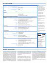
The control electronics unit (CEU) shall be a single rack space
processor providing two separate channels with required
frequency response optimization filters, phase alignment
and required protection limiters specifically designed for the
MM-4 loudspeaker system. The CEU shall provide RMS and
peak limiting to the audio signal feeding the power amplifier
when activated by a driver protection circuit that senses the
power amplifier output. The sensing circuit shall allow each
channel of the CEU to drive several power amplifier channels
and to sense two power amplifier outputs at one time such
that the highest level (voltage) branch of an MM-4 distributed
loudspeaker system will not exceed the power handling of
the drivers and will actuate system protection circuits. A
recessed front-panel low cut boundary EQ filter switch shall
be provided for each channel to allow frequency compensation
to be applied when an optional subwoofer loudspeaker is
employed or for architectural/acoustic boundary conditions.
Each channel of the CEU shall provide a rotary input attenuator,
low-cut filter toggle switch and three LED indicators for signal
level and sense threshold, for the RMS limiter and for the peak
limiter. An on-board regulated power supply shall be included
with externally accessible fuse and all electrical parts shall be
of the highest quality.
The control electronics unit (CEU) shall be the Meyer Sound
MM-4CEU.
MM-4CEU Control Electronics Unit (required)
MM-4CEU
MM-4CEU