


MICA Specifications
1. Recommended maximum operating
frequency range. Response depends
on loading conditions and room
acoustics.
2. Free field, measured with 1/3-octave
frequency resolution at 4 meters.
3. Measured with music referred to 1
meter.
4. At these frequencies, the transducers
produce equal sound pressure levels.
5. Power handling is measured under
AES standard conditions: both
transducers driven continuously for
two hours with band-limited noise
signal having a 6 dB peak-average
ratio.
6. Peak power handling is measured
with both transducers driven for 100
milliseconds with pink noise signal
having a 12 dB peak-average ratio.
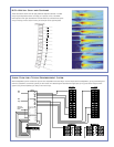
7. The two drivers are coupled to a
100-degree horizontal constant-
directivity horn through a propri-
etary acoustical combining manifold
(REM).
8. Amplifier wattage rating based on
the maximum unclipped burst sine-
wave rms voltage that the amplifier
will produce for at least 0.5 seconds
into the nominal load impedance: 62
V rms low channels and 67 V rms high
channels.
9. Peak power based on the maximum
unclipped peak voltage that the
amplifier will produce for at least
100 milliseconds into the nominal
load impedance: 87 V pk low channels
and 95 V pk high channels.
10. AC power cabling must be of suf-
ficient gauge so that under burst
current rms conditions, cable trans-
mission losses do not drop voltage
below specified operating range at
the speaker.
meyer sound laboratories inc.
2832 San Pablo Avenue
Berkeley, CA 94702
T: +1 510 486.1166
F: +1 510 486.8356
techsupport@meyersound.com
www.meyersound.com
MICA — 04.147.004.01 A
Copyright © 2005
Meyer Sound Laboratories Inc.
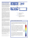
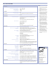
Operating Frequency Range
1
Free Field Frequency Response
2
Phase Response
Maximum Peak SPL
3
Dynamic Range
Horizontal Coverage
Vertical Coverage
Low/Low-Mid Frequency
High Frequency
7
Type
Maximum Common Mode Range
Connectors
Input Impedance
Wiring
DC Blocking
CMRR
RF Filter
TIM Filter
Nominal Input Sensitivity
Input Level
Type
Output Power
8
Total Output
9
THD, IM, TIM
Load Capacity
Cooling
Connector
Automatic Voltage Selection
Safety Agency Rated Operating Range
Turn-on and Turn-off Points
Current Draw:
Idle Current
Max Long-Term Continuous Current (>10 sec)
Burst Current (<1 sec)
10
Ultimate Short-Term Peak Current Draw
Inrush Current
60 Hz - 18 kHz
75 Hz - 17 kHz ±4 dB
1 kHz - 16 kHz ±30°
138 dB
>110 dB
100°
Varies, depending on array length and configuration
1000 Hz
Two high-power 10" cone drivers with neodymium magnets
Nominal impedance: 4 Ω
Voice coil size: 2"
Power handling capability: 1200 W (AES)
5
; 1800 W peak
6
Two 3" compression drivers
Nominal impedance: 8 Ω
Voice coil size: 3"
Diaphragm size: 3"
Exit size: 1.2"
Power handling capability: 360 W (AES)
5
; 720 W peak
6
Differential, electronically balanced
±15 V DC, clamped to earth for voltage transient protection
Female XLR input with male XLR loop output or VEAMall-in-one
connector (integrates AC, audio and network)
10 kΩ differential between pins 2 and 3
Pin 1: Chassis/earth through 220 kΩ, 1000 pF, 15 V clamp network
to provide virtual ground lift at audiofrequencies
Pin 2: Signal +
Pin 3: Signal -
Case: Earth ground and chassis
None on output, DC blocked through signal processing
>50 dB, typically 80 dB (50 Hz–500 Hz)
Common mode: 425 kHz
Differential mode: 142 kHz
Integral to signal processing (<80 kHz)
0 dBV (1 V rms, 1.4 V pk) continuous is typically the onset of
limiting for noise and music
Audio source must be capable of producing a minimum of +20 dBV
(10 V rms, 14 V pk) into 600 Ω inorder to produce maximum peak
SPL over the operating bandwidth of the loudspeaker
Four-channel complementary MOSFET output stages (class AB/H)
3020 W (four channels; 2 x 950 W, 2 x 560 W)
6000 W peak
<.02%
4 Ω low and mid channels; 8 Ω high channels
Forced air cooling, four fans (two ultrahigh-speed reserve fans)
250 V AC NEMA L6-20 twistlock, IEC-309 male, PowerCon, or VEAM
Automatic, two ranges, each with high-low voltage tap
(uninterrupted)
95 V AC - 125 V AC; 208 V AC - 235 V AC, 50/60 Hz
85 V AC - 134 V AC; 165 V AC - 264 V AC
1.1 A rms (115 V AC); 0.55 A rms (230 V AC); 1.3 A rms (100 V AC)
5.4 A rms (115 V AC); 2.7 A rms (230 V AC); 6.2 A rms (100 V AC)
8.7 A rms (115 V AC), 4.3 A rms (230 V AC), 10.0 A rms (100 V AC)
24.6 A rms (115 V AC), 12.3 A rms (230 V AC), 28.3 A rms (100 V AC)
11 A rms (115 and 100 V AC), 15 A rms (230 V AC)
Equipped with two-conductor twisted-pair network, reporting
all operating parameters of amplifiers to system operator’s host
computer
Notes:
Acoustical
Coverage
Crossover
4
Transducers
Audio Input
Amplifier
AC Power
RMS Network
EuropeanOffice:
MeyerSoundLab. GmbH
CarlZeissStrasse13
56751Polch,Germany
MadebyMeyerSoundLaboratories
Berkeley,California USA