


8.4
0.6 0.7
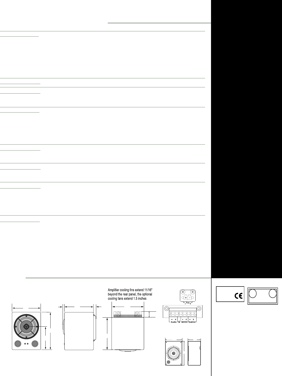
PHYSICAL DIMENSIONS
ALL UNITS IN INCHES
Meyer Sound Laboratories, Inc.
2832 San Pablo Avenue
Berkeley, CA 94702
tel: 510.486.1166
fax: 510.486.8356
e-mail: techsupport@meyersound.com
http: www.meyersound.com
U
L
C
U
L
®®
LISTED
3K59
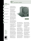
COMMERCIAL
AUDIO SYSTEM
Meyer Sound Laboratories
has devoted itself to
designing, manufacturing,
and refining components
that deliver superb sonic
reproduction. Every part of
every component is
designed and built to
exacting specifications
and undergoes rigorous,
comprehensive testing
in the laboratories.
Research remains an
integral, driving force
behind all production.
Meyer strives for sound
quality that is predictable
and neutral over an
extended lifetime and
across an extended range.
Made by Meyer Sound, Berkeley, CA, USA
European Office:
Meyer Sound Europe
Dalston House
39-49 Hastings Street
Luton Bedfordshire
England, LU1 5BE
© 1998 Meyer Sound Laboratories, Inc.
All rights reserved
11.0
8.4
6.75
8.4
8.4
1.5
HM-1 - 04.039.002.01B
Rear Panel
TopSideFront
Acoustical
1
(each loudspeaker)
Coverage
Transducers
Dual-Concentric
Drivers (magnetically
shielded)
Audio Input
Amplifiers
AC-Power
Physical
Notes
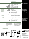
HM-1 SPECIFICATIONS
Frequency Range
2
Free Field
Half-space
3
Free Field with Subwoofer
4
Phase Response
5
Maximum SPL
6
Off-axis Amplitude Response
Crossover
Signal to Noise Ratio
(-6 dB points)
Low Frequency
High Frequency
Subwoofer (optional)
Connector
Type
Impedance
XLR Wiring
RF Filter
Common Mode Rejection Ratio
Type
Output Power
THD, IM, TIM
Voltage
Current
9
Dimensions
Weight
Protective Grill
Enclosure/Finish
42 Hz - 20 kH
2
±2.5 dB 100 Hz – 20 kHz; –6 dB 42 Hz – 100 Hz
±2.5 dB 90 Hz – 20 kHz; –3 dB 42 Hz – 90 Hz
±2.5 dB 42 Hz – 20 kHz
±20° 250 Hz – 15 kHz
Without Sub: 116 dB SPL; With Sub: 120 dB SPL
±3.5 dB 100 Hz – 20 kHz up to 45° coverage
7
Complex roll-off shape, ≈ 3 kHz equal acoustic amplitude
>100 dB (A-weighted noise floor to max SPL)
100° H; 100° V
7” graphite cone driver
1” soft-dome tweeter
10” cone driver (not shielded)
Options are 1 female XLR or a pluggable terminal strip
Differential balanced input circuit
8
10 kΩ differential (between pins 2 and 3)
Pin 1: chassis; Pin 2: + signal; Pin 3: – signal
Common Mode: 425 kHz low-pass; Differential Mode:
142 kHz low-pass
>80 dB (50 Hz – 1 kHz); typically 90 dB
Complementary MOSFET output stages class A/B, bridged
400 Watts RMS, 200 Watts/channel at 4 Ω (with subwoofer)
<.02 %
Nominal: 48 VDC; Maximum: 52 VDC; Minimum: 35 VDC;
Typical: 2.0 Arms, 3.5 Apk; Maximum in limiting:
3.0 Arms, 5.0 Apk
Height: 11.0”; Width: 8.4”; Depth: 9.7”, 10.5” with
fan attachment
11.0 lb (5.0 kg); shipping: 13.5 lb (6.1 kg)
Removable perforated steel grill causes < 0.5 dB
response variation
All birch plywood/black textured
1. Measurements are taken at 1 m on-axis,
1
/3
octave, unless otherwise stated.
2. Amplitude tolerance depends on loading
conditions and whether the subwoofer is used.
3. Flush-mounted into single boundary surface.
4. Subwoofer adds approximately 8 dB
42 – 100 Hz.
5. Phase variation from pure delay and minimum
phase removed.
6. Pink noise or music.
7. A gradual amplitude attenuation occurs as the
angle increases beyond 45°. Greater attenuation
occurs at 2 kHz and beyond 10 kHz. There are
no response peaks.
8. Capacitively coupled; accepts up to ±50 VDC
common mode.
9. Idle current @ 0.4 A; using the slaved
subwoofer increases stated currents by @ 20%.
12.3
17.5
9.3
OPTIONAL HM-1 SUBWOOFER