


Operating Instructions
Meyer Sound Laboratories, Inc.
2832 San Pablo Avenue
Berkeley, CA 94702
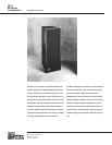
DS-2
Mid-Bass
Loudspeaker
3. Crossover to main system – All cabinets in the DS-2
array and main system should first be tested, then placed
in the position in which they will be operated.
• With the system master level control at minimum, in-
put pink noise to the system, then set a comfortable
measuring level. Position the microphone on the axis
of the system, 6 feet or more distant.
• Note the system response in the mid-bass region. A
cancellation of approximately 6 dB centered at 160 Hz
indicates a polarity reversal between the DS-2’s and
the main system.
• If in doubt, reverse the polarity of the DS-2’s and ob-
serve the response.
4. Crossover to subwoofers (optional) – If you elect to
use subwoofers to reproduce the 30-60 Hz octave, they
must first be tested individually for correct polarity (refer
to the Operating Instructions for the subwoofer system).
It is common to place subwoofers at some distance from
the main system (on the ground below a flown array, for
Placement and
Arraying
The DS-2 is designed to perform extremely well in arrays
with Meyer Sound MSL-3A‘s or MSL-10A‘s, and main-
tains a well-defined 1/R image at the rear of the cabinet.
Its rigging points are strengthened with steel reinforcing
rods running the length of the cabinet from top to bottom,
and a single DS-2 will support two MSL-3A or DS-2 cabi-
nets suspended below it.
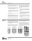
The diagrams below illustrate some examples of DS-2 ar-
rays. Where units are arrayed in a single block, they
should always be placed with adjacent cabinet faces
A. Minimum
configuration
B. Block of
four units
C. Interleaved with
MSL-3A cabinets
D. Arrayed with
MSL-10A cabinets
example). In part because of the long wavelengths in-
volved, propagation delay can cause a cancellation at the
crossover to the main system. For this reason, it is al-
ways necessary to check the subwoofer crossover once
the system has been installed in the position in which it
will be operated.
• Connect the subwoofer system input to the D-2 Sub-
woofer output, and set the D-2 Mode switch to the
“DS-2 & Sub” position (refer to the D-2 Operating
Instructions).
• With the system master level control at minimum, in-
put pink noise to the system, then set a comfortable
measuring level. Position the measurement micro-
phone on the axis between the subwoofers and the
system, 6 feet or more distant.
• Note the system response in the bass region. A can-
cellation of approximately 6 dB centered at 50 Hz indi-
cates a polarity reversal between the subwoofers and
the main system.
• If in doubt, reverse the subwoofer polarity using the
D-2 Sub Polarity switch and observe the response.
flush to one another. Spreading the cabinets does not
substantially alter the horizontal coverage of the array be-
cause of the long wavelengths involved.
Until the array reaches large dimensions (six or more
tight-packed cabinets), horizontal coverage remains a
constant 120° (± 60°) as units are added to the array
(acoustic power increases substantially with each addi-
tional cabinet). In arrays with MSL-3A’s, large array size
may be achieved by interleaving DS-2’s and MSL-3A’s
as shown in Diagram C.