


CQ-1 specifications
architect specifications
meyer sound laboratories inc.
2832 San Pablo Avenue
Berkeley, CA 94702
T: +1 510 486.1166
F: +1 510 486.8356
techsupport@meyersound.com
www.meyersound.com
CQ-1 — 04.041.011.01 C
Copyright © 2004
Meyer Sound Laboratories Inc.
All rights reserved
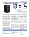
The loudspeaker shall be a self-powered, full range system. The
transducers shall consist of a 15-inch diameter cone driver and
a 1.5-inch throat, 4-inch diaphragm compression driver on an
80-degree horizontal by 40-degree vertical constant-Q horn.
The loudspeaker system shall incorporate internal processing
electronics and a two-channel amplifier. Processing functions
shall include equalization, phase correction, driver protection
and signal division for the high- and low-frequency sections.
The crossover point shall be 700 Hz. Each amplifier channel
shall be class AB/H with complementary MOSFET output stages.
Burst capability shall be 620 watts each channel (1240 watts
total) with nominal 8-ohm resistive load. Distortion (THD, IM,
TIM) shall not exceed 0.02 percent. Protection circuits shall
include TruPower limiting.
Performance specifications for a typical production unit shall
be as follows: Operating frequency range shall be 35 Hz to 18
Notes:
kHz. Phase response shall be ±90 degrees from 50 Hz to 16 kHz.
Maximum peak SPL shall be 136 dB at 1 meter. Beamwidth shall
be 80 degrees horizontal from 500 Hz to 16 kHz and 40 degrees
vertical from 1500 Hz to 12 kHz.
The audio input shall be electronically balanced with a 10 kOhm
impedance and accept a nominal 0 dBV (1 V rms, 1.4 V pk) signal
(+20 dBV to produce maximum peak SPL). Connectors shall be
XLR (A-3) type male and female or VEAM all-in-one (integrates
AC, audio and network). RF filtering shall be provided. CMRR
shall be greater than 50 dB (typically 80 dB 50 Hz to 500 Hz).
The internal power supply shall perform automatic voltage
selection, EMI filtering, soft current turn-on and surge sup-
pression. Powering requirements shall be nominal 100 V, 110 V
or 230 V AC line current at 50 Hz or 60 Hz. UL and CE operating
voltage ranges shall be 95 to 125 V AC and 208 to 235 V AC.
Current draw during burst shall be 15 A at 115 V AC and 8 A at
230 V AC. Current inrush during soft turn-on shall not exceed 7
A at 115 V AC. AC power connectors shall be locking NEMA L6-
20 connector, IEC 309 male or VEAM.
The loudspeaker system shall provide facilities for installing the
optional RMS remote monitoring and control system.
All loudspeaker components shall be mounted in an acoustically
vented trapezoidal enclosure constructed of birch plywood
with a hard black textured finish. The front protective grille
shall be perforated hex metal covered by charcoal gray foam.
Dimensions shall be 21.00” wide x 30.00” high x 22.20” deep
(533 mm x 762 mm x 564 mm). Weight shall be 130 lbs (58.97 kg).
Rigging points shall be four ring and stud pan fittings, two each
top and bottom, rated at 500 lbs (226.80 kg) per fitting at a 5:1
safety factor; 3/8-inch or metric M10 nut plates are optional.
The loudspeaker shall be the Meyer Sound CQ-1.
1. Recommended maximum operating
frequency range. Response depends
on loading conditions and room
acoustics.
2. Free field, measured with 1/3-octave
frequency resolution at 4 meters.
3. Measured with music at 1 meter.
4. At this frequency, the low- and high-
frequency transducers produce equal
sound pressure levels.
5. Power handling is measured under
AES standard conditions: transducer
driven continuously for two hours
with band-limited noise signal having
a 6 dB peak-average ratio.
6. Amplifier wattage rating is based
on the maximum unclipped burst
sine-wave rms voltage the amplifier
will produce into the nominal load
impedance. Both channels 70 V rms
(100 V pk) into 8 ohms
EuropeanOffice:
MeyerSoundLab. GmbH
CarlZeissStrasse13
56751Polch,Germany
MadebyMeyerSoundLaboratories
Berkeley,California USA
Operating Frequency Range
1
Frequency Response
2
Phase Response
Maximum Peak SPL
3
Dynamic Range
Low Frequency
High Frequency
Type
Maximum Common Mode Range
Connectors
Input Impedance
Wiring
DC Blocking
CMRR
RF Filter
TIM Filter
Nominal Input Sensitivity
Input Level
Type
Output Power
6
THD, IM, TIM
Load Capacity
Cooling
Connector
Voltage Selection
Safety Agency Rated Operating Range
Turn-on and Turn-off Points
Current Draw: Idle Current
Max Long-Term Continuous Current (>10 sec)
Burst Current (<1 sec)
Ultimate Short-Term Peak Current Draw
Inrush Current
35 Hz - 18 kHz
40 Hz - 16 kHz ±4 dB
50 Hz - 16 kHz ±90°
136 dB
>110 dB
80° Horizontal x 40° vertical
700 Hz
One 15" cone driver
Nominal impedance: 8 Ω
Voice coil size: 3"
Power-handling capability: 600 W (AES)
5
One 4" diaphragm driver
Nominal impedance: 8 Ω
Voice coil size: 4"
Diaphragm size: 4"
Exit size: 1.5"
Power handling capability: 250 W (AES)
5
Differential, electronically balanced
±15 V DC, clamped to earth for voltage transient protection
Female XLR input with male XLR loop output or VEAM all-in-one
(integrates AC, audio and network)
10 kΩ differential between pins 2 and 3
Pin 1: Chassis/earth through 220 kΩ, 1000 pF, 15 V clamp network to
provide virtual ground lift at audio frequencies
Pin 2: Signal +
Pin 3: Signal - (Polarity can be changed on user panel)
Case: Earth ground and chassis
None on input; DC blocked through signal processing
>50 dB, typically 80 dB (50 Hz – 500 Hz)
Common mode: 425 kHz; Differential mode: 142 kHz
<80 kHz, integral to signal processing
0 dBV (1 V rms, 1.4 V pk) continuous average is typically the onset of
limiting for noise and music.
Audio source must be capable of producing a minimum of +20 dBV
(10 V rms, 14 V pk) into 600 Ω to produce maximum peak SPL over the
operating bandwidth of the loudspeaker
Two-channel complementary MOSFET output stages (class AB/H)
1240 W (620 W/channel)
<.02%
8 Ω each channel
Forced air cooling, two fans total (one ultrahigh-speed reserve fan)
250 V AC NEMA L6-20 (twistlock) inlet, IEC 309 male inlet, or VEAM
Automatic, two ranges, each with high-low voltage tap (uninterrupted)
95 V AC - 125 V AC; 208 V AC - 235 V AC; 50/60 Hz
85 V AC - 134 V AC; 165 V AC - 264 V AC; 50/60 Hz
0.640 A rms (115 V AC); 0.320 A rms (230 V AC); 0.850 A rms (100 V AC)
8 A rms (115 V AC); 4 A rms (230 V AC); 10 A rms (100 V AC)
15 A rms (115 V AC); 8 A rms (230 V AC); 18 A rms (100 V AC)
22 A pk (115 V AC); 11 A pk (230 V AC); 25 A pk (100 V AC)
7 A pk (115 V AC); 7 A pk (230 V AC); 10 A pk (100 V AC)
Equipped for two conductor twisted-pair network, reporting amplifier
operating parameters to system operator’s host computer.
Acoustical
Coverage
Crossover
4
Transducers
Audio Input
Amplifier
AC Power
RMS Network (optional)