


4
McIntosh Acoustic Engineers have further refined the con-
cept of line source column in the XRT1K Loudspeaker to
provide superior sound reproduction in a full range system.
It uses the same acoustic technology found in the famous
XRT2K Column Loudspeakers. The technology has been
refined over the years and is now the 6th generation of the
design and provides superior
quality sound reproduction in a
full range system.
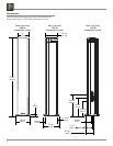
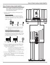
The High Frequency Sec-
tion utilizes a patented Column
Design
1
with multiple three-
quarter inch Titanium Dome
Tweeters and two inch Midrange
Inverted Titanium Dome Driv-
ers. Refer to figures 1 and 2.
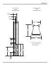
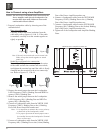
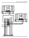
Since the audio power fed
to a column is distributed
among all the drivers, each
driver does not have to work
as hard, resulting in greater
power handling capability
and a dramatic reduction
in distortion. The Sound
Waves from the Column
produce a Cylindrical Wave
Front with a stable symmet-
rical horizontal
sound disper-
sion to minimize
undesirable
floor and ceiling
reflections that
could detract
from a stable
sound image. In
the illustration the Loudspeaker on the left side produces a
Cylindrical Wave Front and the Loudspeaker on the right
side produces a conventional Spherical Wave Front. Refer
to figure 3.
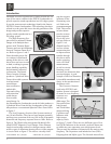
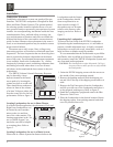
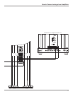
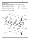
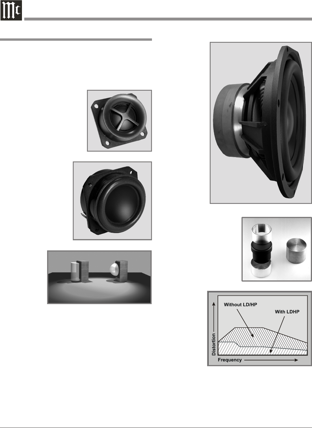
The Low Frequency Section of the System consists of
two 10 inch Woofers. They have a large magnet assembly
and long cone excursions with very low levels of harmonic
distortion and frequency response down to 16Hz. Refer to
figure 4. The Woofer also incorporates McIntosh’s Pat-
ented LD/HP
2
Magnetic Circuit Design. Finite Element
Analysis and testing resulted in a design concept which
utilizes a pair of aluminum shorting sleeves in the magnet-
ic circuit. Refer to figure 5. The sleeves virtually elimi-
nate the negative
influence of the
fluctuating voice
coil field on the
permanent magnet
field. This results
in lower distor
-
tion due to more
linear magnetic
flux in the voice
coil gap. Refer to
figure 6. Ad-
ditional benefits
are less volume
compression due
to improved heat
transfer through
the sleeves and a
cooler operating
voice coil. Both
measurements,
as well as critical
listening, reveal
ten times less distortion than
previous designs. A good
example of this low distortion
is incredible smoothness and
clarity in the reproduction of
the human voice.
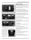
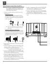
The Crossover Network
used in the XRT1K Loud-
speaker System is designed
to ensure an even frequency
response over
the entire au-
dible range. The
Network utilizes
both Second
and Third Order
design utilizing
Capacitors and
Inductors with
high current
capacity. Refer
to figures 7, 8 and 9. There are two different types of low
loss (DCR) Inductors in the network, each one chosen not
to exhibit any core saturation even at high power levels.
This prevents the addition of distortion to the music at any
frequency. The Capacitors used include low loss (ESR)
Polypropylene and Mylar types. The Network also utilizes
Introduction
Figure 2
Figure 1
Figure 4
1
COLUMN Pat. No. 4,267,405
2
LD/HP Pat. No 5,151,943
Figure 6
Figure 3
Figure 5
LD/HP
Conventional