


5
4
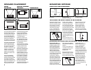
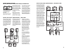
SPEAKER PLACEMENT
SUBWOOFER
SURROUND SPEAKERS
5
–6 ft
(1.5–1.8m)
FRONT
SPEAKERS
0–2 ft
(0–0.6m)
The front speakers should be
placed the same distance
from each other as they are
from the listening position.
They should be placed at
about the same height from
the floor as the listeners’
ears will be, or they may be
angled toward the listeners.
The center channel speaker
should be placed directly
above or below the televi-
sion, and no more than two
feet above or below the
tweeters of the left and right
speakers. It is often con-
venient to set the center
speaker on top of the tele-
vision set, as shown in the
drawing.
The surround speakers
should be placed slightly
behind the listening position
and, ideally, should face
each other and be at a
level
higher than the listeners’
ears.
If that is not possible, they
may be placed on a wall
behind the listening position,
facing forward. Additional
satellites may be purchased
separately for use in 6.1- or
7.1-channel systems.
Generally, it is best to aim
all of the speakers (except
the subwoofer) toward the
listening position at about
ear
-level height.
The low-frequency material
reproduced by the subwoofer
is mostly omnidirectional,
and this speaker may be
placed in a convenient loca-
tion in the room. However,
bass reproduction will be
maximized when the sub-
woofer is placed in a corner
along the same wall as the
front speakers. Experiment
with subwoofer placement
by temporarily placing the
subwoofer in the listening
position and moving around
the room until the bass
reproduction is best. Place the
subwoofer in that location.
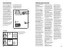
CENTER CHANNEL
SPEAKER
MOUNTING OPTIONS
On shelves.
On the wall. Wall
brackets are included.
On optional stands.
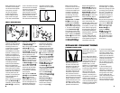
SATELLITES AND SURROUNDS
Prepare the speaker wire as
described on page 7. Thread
the two conductors through
the two holes in the stand
bracket. Make sure to pre-
serve the proper polarity
(+ and – connections) by
threading the positive con-
ductor through the hole on
the left, and the negative
conductor through the hole
on the right, looking at the
front of the stand. Push down
on the red speaker terminal
and insert the bare end of the
positive wire into the hole
under the red cap. Release
the cap, and tug gently on the
wire to make sure that the
connection is snug. Follow
the same procedure to con-
nect the negative wire to its
terminal.
Gently pull the slack out of
the wire and screw the shelf
stand onto the back of the
speaker in two places, as
shown. The shelf stand
screws may be found in
Hardware Bag A. Use the
larger screw in the upper
screw hole, and the smaller
screw in the lower screw hole.
ATTACHING THE SHELF STAND TO THE SPEAKER
MOUNTING THE SATELLITES ON OPTIONAL FLOOR STANDS
Important Safety Note: The
supplied floor stand adapters
facilitate installation with a
variety of general-purpose
floor stands available from
many manufacturers. Since
different stands will have
different weight capacities
and stability characteristics, it
is the customer’s responsibility
to check with the stand
manufacturer or dealer to
determine whether that spe
-
cific stand is capable of han-
dling the weight and propor
-
tions of these loudspeakers in
a safe and stable manner. JBL
disclaims any liability for the
selection of suitable floor
stands and/or correct compat-
ibility between the selected
stand and these satellite loud-
speakers.
The floor stand adapters are
compatible with floor stands
equipped with a 1/4"-20
threaded insert.
Prepare the speaker wire as
described on page 7. Thread
the two conductors through
the two holes in the floor stand
adapter. Make sure to
preserve the proper polarity
(+ and – connections) by
threading the positive
conductor through the hole
on the left, and the negative
conductor through the hole on
the right, looking at the front of
the adapter. Push down on the
red speaker terminal and
insert the bare end of the
positive wire into the hole
under the red cap. Release
the cap, and tug gently on
the wire to make sure that
the connection is snug.
Follow the same procedure
to connect the negative wire
to its terminal.
+
–
+
–
+
–
+
–
+
–
+
–