part of the outer insulation; or a print-
ed “+” marking on one of the insula-
tors. It does not make any difference
which of the two strands of wire go to
(+) and (–) on the speakers and
amplifier, as long as all speakers
used in your system are connected
identically. Push down on the button
below the terminal and insert the wire
through the hole.
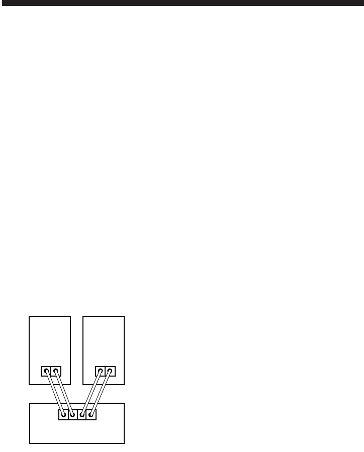
For each channel, the red terminal on
all loudspeakers should be connected
to the red or (+) speaker connection
terminal on the receiver or amplifier,
and the black to black or (–) speaker
connection terminal (see Fig. 3).
Connecting the loudspeakers in this
manner ensures that they will be in
phase; that is, work together rather
than in opposition. This is very
important when connecting sev-
eral speakers together in a Dolby
Pro-Logic AV application. Connecting
the loudspeakers out of phase will
not damage them, but will result in
less bass and poor imaging.
When connecting the MR Center or
other MR Series speakers to a Dolby
Pro-Logic AV receiver, refer to the
instructions accompanying your AV
component for use of the “test tone”
to properly balance the sound output
from each speaker. The use of the
“test tone” and the controls on your
AV receiver will enable you to cor-
rectly balance the level (volume) of
sound coming from each speaker in
your Dolby Pro-Logic application.
Hooking Up Multiple Sets
of Speakers
If your receiver has two complete
sets of speaker terminals (“A” and
“B”), it’s possible to hook up an addi-
tional pair of speakers for
simultane-
ous
sound in another room. However,
some speakers may not be usable as
a second pair if you want to play two
sets at once. Before hooking up
another set of speakers besides your
MR Series loudspeakers, check the
following:
1. Your amplifier’s minimum load
impedance.
2. The nominal impedance of the
second set of speakers. Both of
these specifications are expressed in
ohms and both can be found in the
owner’s manuals which came with
your speakers and amp/receiver. The
receiver’s minimum load impedance
is determined by whether or not
power ratings are given for 4 ohms.
This is because two sets of 8 ohm
speakers will present a 4 ohm load to
the receiver. The MR speaker, when
combined with an 8 ohm speaker,
produces an impedance sufficiently
close to 4 ohms. For example, the
following entry in an amplifier owner’s
manual...
POWER:
A)100 watts RMS into 8 ohms, both chan-
nels driven, 20-20kHz with less than
0.02%THD
B) 160 watts RMS into 4 ohms, both
channels driven, 20-20kHz with less than
0.02% THD.
Part B indicates that the amplifier can
handle 4-ohm combined impedances
created by two sets of speakers.
4
Left
Speaker
Amplifier/Receiver
Right
Speaker
Red Blk.
(+)
++
(–)
Red
RL
Blk.
(+) (–)
Fig. 3
MR Series OM 7/28/98 10:32 AM Page 4


