


4
EXISTING CONSTRUCTION
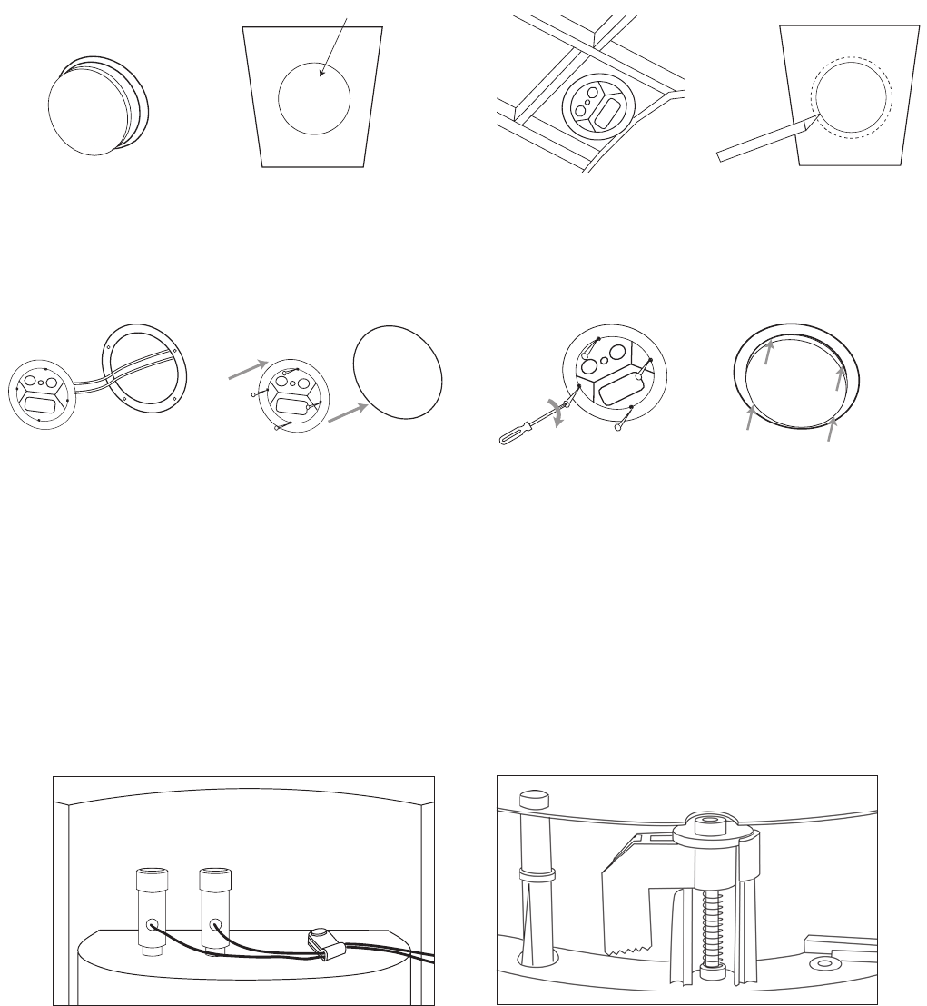
1. Remove the plastic paint
shield from the speaker frame.
2. Determine the correct
speaker location.
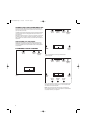
NOTE: Use the included
template when cutting the
drywall.
Template
Ceiling Joist
Ceiling Joist
3.
NOTE: Always allow at
least a 1/2 inch between
a ceiling stud/joist and the
speaker cutout, or the
locking tabs will not be
able to swivel into place.
4. Ensure that the drywall or plywood
board or other appropriate wallboard
is at least a 1/2-inch thick, and confirm
that the board material is capable of
withstanding the weight of the speaker
you will be installing. Cut the drywall.
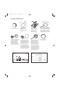
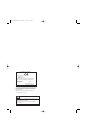
5. Connect the speaker wires to
the speaker. It is recommended
that the nylon cable-strain
relief tab, located next to the
speaker terminals, be used
to help prevent the speaker
wires from being accidentally
dislodged (see Figure 5, below).
6. Make sure all four locking tabs
are properly positioned against
the locking tab stops that are
located on the speaker frame (see
Figure 6, below). After confirming
this, carefully place the frame
assembly in the ceiling and con-
firm that there is no more than
1/8-inch play between the frame
and the ceiling cutout. After posi-
tioning the speaker in the mounting
location, back each screw out one
full turn (turn counterclockwise).
7. Screw down each of the four
Phillips-head screws, alternating
between the four screws. The
locking tabs will swivel into
place and secure the unit to the
rear surface of the ceiling. Hand-
tighten with a nonpowered,
straight-handle regular screw-
driver only. Do not use a socket
wrench, a powered screwdriver,
a drill or any other powered tool.
Confirm that the speaker is firmly
and securely held in place and
that all four locking tabs are firmly
resting against the ceiling.
8. Attach the metal grille
and logo, if desired.
Figure 6.
Figure 5.
StudioLS360Com.qxd 7/25/07 4:18 PM Page 4