


9
Adjustable wall brackets are included for the two speakers and transmitter
module. The included brackets are for wall-mounting only. It is not to be used
for ceiling mounting. Ceiling mounting of the Control 2.4G transmitter and/or
speakers is not recommended, regardless of bracket used.
Wall-Mounting the Speakers
Using Wall Brackets Provided
Important Safety Note: Proper selection of mounting hardware not included
herein, and proper assembly and installation of brackets, including, but not
limited to, selection of appropriate weight-bearing support and bracket use
with the specified speaker only is the exclusive responsibility of the customer.
Manufacturer disclaims any liability for the selection of mounting hardware
and/or bracket installation.
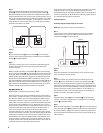
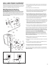
A. Loosen and remove the molded nut
(2)
by turning it counterclockwise. Use
the supplied metal bar (5) if necessary by inserting it in one of the holes on
the molded nut
(2)
.
B. Pull the ball/shaft
(3)
out of the wall bracket
(4)
.
C. Slide the molded nut
(2)
onto the ball/shaft
(3)
with threaded opening facing
the ball, and thread on the metal nut
(1)
all the way onto the ball/shaft
(3)
,
with the nut’s (1) ”knurled” surface facing away from the ball.
D. Screw the ball/shaft (3) into the threaded 1/4"-20 insert on the back of the
speaker cabinet
(6)
until it is fully seated against the bottom of the insert.
Back out the ball-shaft assembly 1/2 of a turn and tighten the nut against the
speaker. If the ball and shaft assembly is not backed out before tightening
the nut, performing Step G below may dislodge the threaded insert in the
speaker housing and permanently damage the speaker.
E.
Tighten the ”knurled” nut (1) using a crescent wrench until it is firmly seated
against the back of the speaker and has fully locked the ball/shaft
(3)
and the
speaker cabinet together. Please note that once this nut is tightened, it may
embed some marks on the back of the speaker where the attachment is
made. However, these marks will be covered by the nut (1).
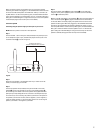
F. The backup cord
(8) is
provided as an additional measure to prevent the fall
of the speaker in case the speaker becomes detached from the wall bracket.
One of the two lower screws
(9)
that attach the wall bracket
(4)
to the wall will
need to go through the eyelet
(11)
at the end of the cord before going through
the wall-bracket hole. Mount the wall bracket
(4)
onto a wood stud on the wall,
using #10, minimum 1-inch-long, panhead wood screws. Make sure that all four
screws are driven into the stud, not drywall. If the bracket needs
to be mounted on drywall, the use of properly selected and installed wall
anchors and screws is essential. Make sure that the screw head is at least
0.36 of an inch (approximately 3/8 of an inch) or larger in diameter so that it can
properly hold the backup cord eyelet
(11)
.
G. Holding the speaker cabinet
(7)
with both hands, reinsert the ball portion of
the ball/shaft
(3)
into the wall bracket
(4)
.
H. Hand-tighten the molded nut
(2)
while positioning the speaker for the intended
orientation.
I. Once the orientation of the speaker is finalized, use the metal bar (5) in one
of the holes on the molded nut
(2)
and tighten securely
.
J. Securely attach the other end
(10)
of the backup cord
(8)
to the Control 2.4G
by engaging it through the bar (12) on the back speaker.
Also included with the system is a wall-mount holder for the active speaker’s
power supply. If desired, you may attach this holder to the wall and insert the
speaker’s power supply.
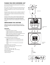
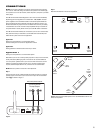
WALL AND STAND PLACEMENT
TO LEFT SPEAKER
+–
TO LEFT SPEAKER
+–
CORRECT INCORRECT