


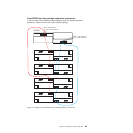
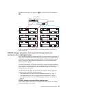
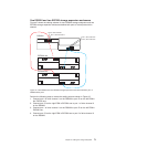
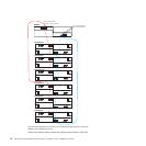

One DS5020 and two EXP520 storage expansion enclosures
Figure 47 shows the cabling scheme for one DS5020 storage subsystem and two
EXP520 storage expansion enclosures behind both ports of a dual-ported drive
channel.
Perform the following steps to create the cabling scheme shown in Figure 47:
1. Connect port 2 of drive channel 1 on the DS5020 to port 1B on the left ESM in
the EXP520 one.
2. Connect port 1B on the right ESM in EXP520 one to port 1 of drive channel 2
on the DS5020.
3. Connect port 1 of drive channel 1 on the DS5020 to port 1B on the left ESM in
EXP520 two.
4. Connect port 1B on the right ESM in EXP520 two to port 2 of drive channel 2
on the DS5020.
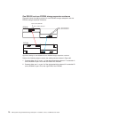
1A
1B
DS5020
Port 2, drive channel 1
1A
1B
1A
1B
Port 1, drive channel 1
Port 1, drive channel 2
Port 2, drive channel 2
1A
1B
EXP520 one
EXP520 two
Figure 47. One DS5020 and two EXP520 storage expansion enclosures behind a pair of
DS5020 drive ports
Chapter 3. Cabling the storage subsystem 71