


USING TWO RECEIVERS IN HIGH-SECURITY MODE
If the control supports two receivers and you plan to use them
in the high-security mode perform the following:
1. Enroll the transmitters into the receivers one at a time, by
disconnecting Receiver #2, and enrolling as described in
“Activating High Security Mode” (above).
2. Disconnect Receiver #1, reconnect Receiver #2, and repeat
the enrollment procedure. This process ensures proper High
Security operation with both receivers.
Temporarily disable the receivers’ supervisory
zones while enrolling, to prevent them from going
into “trouble” when disconnected. After enrolling,
re-enable the supervisory zones.
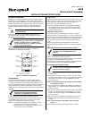
REPLACING THE BATTERY
The LED will not flash during transmission if the battery is
low. To replace the battery perform the following steps.
1. Slide out the battery tray located at the bottom of the 5878.
2. Carefully remove the battery.
3. Press and hold any button for at least one second.
4. Insert a new battery in the tray as shown in Figure 2.
Positive (+) end must face up. Use Maxell CR2032,
Duracell DL 20325, or Varta CR2032 lithium battery only.
5. Slide the battery back into the 5878.
6. Press any button and verify that the LED flashes.
Improper installation will result in damage
to the battery.
BATTERY
AWAY
STAY
1
2
3
4
NOTE
POSITIVE (+) SIDE
MUST FACE UP
5878-002-V0
Figure 2 – Battery Replacement
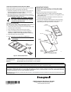
MOUNTING THE 5878
The 5878 can be mounted directly to a wall or other surface
using two-sided (double-stick) tape or by using the provided
back plate.
Mount the 5878 using the back plate as follows:
1. Mount the back plate to a sturdy wall using self-tapping
screws supplied (anchors for drywall are not supplied) or two-
sided adhesive tape.
2. Install the 5878 onto the backplate and slide it downward
until the locking device engages.
3. To remove the 5878 from the back plate release the locking
mechanism by pushing it towards the wall, and then care-
fully sliding the 5878 upward until it is released.
STAY
AW
AY
1
2
3
4
5878-003-V0
WALL OR
MOUNTING
SURFACE
LOCKING
DEVICE
BACK PLATE
5878 WALL
TRANSMITTER
MOUNTING
SCREWS (2)
(TYP)
Figure 3 – Installing the 5878
SPECIFICATIONS
Unit Dimensions: 4.5 in (114.3mm) x 2.75 in (69.85mm) x .5 in (12.7mm)
Battery: Maxell CR2032, Duracell DL 20325, or Varta CR2032
FOR WARRANTY INFORMATION AND FOR DETAILS REGARDING THE LIMITATIONS OF THE ENTIRE ALARM SYSTEM, REFER TO THE INSTALLATION
INSTRUCTIONS FOR THE RECEIVER/CONTROL WITH WHICH THIS DEVICE IS USED.
FCC AND INDUSTRY CANADA STATEMENT
THIS DEVICE COMPLIES WITH PART 15 OF FCC RULES AND RSS210 OF INDUSTRY CANADA. OPERATION IS SUBJECT TO THE FOLLOWING TWO
CONDITIONS: (1) THIS DEVICE MAY NOT CAUSE HARMFUL INTERFERENCE, AND (2) THIS DEVICE MUST ACCEPT ANY INTERFERENCE RECEIVED,
INCLUDING INTERFERENCE THAT MAY CAUSE UNDESIRED OPERATION.
THE USER SHALL NOT MAKE ANY CHANGES OR MODIFICATIONS TO THE EQUIPMENT UNLESS AUTHORIZED BY THE INSTALLATION AND SETUP GUIDE
OR THE USER GUIDE.
‡K14347GŠ
K14347 6/06 Rev. A
12800 Brookprinter Place,Poway, CA 92064
Copyright 2006 © Honeywell International Inc.
www.honeywell.com/security