


gives an SPL of 100 dB @1m with -6 dBu
input level.
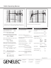
Setting tone controls
The response of the system may also have
to be adjusted to match the acoustic envi-
ronment. The adjustment is done by setting
the three tone control switch groups ‘treble
tilt’, ‘bass tilt’ and ‘bass roll-off’ on the rear
panel of the amplifier. The factory settings
for these controls are ‘All Off’ to give a flat
anechoic response. See Table 1 for sug-
gested tone control settings. Figure 5 shows
the effect of the controls on the anechoic
response. Always start adjustment by setting
all switches to ‘OFF’ position. Then set only
one switch to the ’ON’ position to select the
response curve needed. If more than one
switch is set to ‘ON’ (within one switch group)
the attenuation value is not accurate.
Vertical / horizontal mounting
The speakers are normally delivered set
up for vertical mounting. Horizontal mount-
ing should be avoided due to the increased
likelihood of early reflections that degrade
the the direct sound. If horizontal mounting
is needed the DCW plate may be rotated so
that the Genelec logo remains horizontal by
removing the four corner screws of the DCW
and carefully lifting and turning the DCW.
Console top mounting
If the 1030A’s are used for near field monitor-
ing, avoid mounting them on the meter bridge
of the console. Instead position the speakers
slightly behind the console by using floor
stands or wall mounts. This prevents the
first reflections from the console surface from
coloring the sound.
Maintenance
No user serviceable parts are to be found
within the amplifier unit. Any maintenance
or repair of the 1030A unit should only be
undertaken by qualified service personnel.
Safety considerations
Although the 1030A has been designed
in accordance with international safety
standards, to ensure safe operation and to
maintain the instrument under safe operating
conditions, the following warnings and cau-
tions must be observed:
1. Servicing and adjustment must only
be performed by qualified service
personnel. The amplifier’s rear panel must
not be opened.
2. Do not use this product with an
unearthed mains cable as this may lead to
personal injury.
3. To prevent fire or electric shock, do not
expose the unit to water or moisture. Do
not place any objects filled with liquid,
such as vases on the speaker or near it.
4. Note that the amplifier is not
completely disconnected from the AC
mains service unless the mains power
cord is removed from the amplifier or the
mains outlet.
WARNING!
This equipment is capable of producing
sound pressure levels in excess of 85 dB,
which may cause permanent hearing
damage.
Accessories
Order code
Protective grille
1030-409
Wall mount
1030-404-V/H*
Floor stand
1030-405-V/H*
*State the desired speaker orientation
V=vertical or H=horizontal when ordering
these accessories.
Guarantee
This product is supplied with one year guar-
antee against manufacturing faults or defects
that might alter the performance of the 1030A
unit. Refer to supplier for full sales and guar-
antee terms.
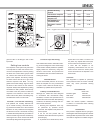
Figure 1. Amplifier panel layout of the 1030A
Figure 2. Location of the acoustic axis
Speaker Mounting
Position
Treble tilt
Bass tilt
Bass roll-off
Flat anechoic response
None
None
None
Free standing in a
damped room
None
-2 dB
None
Free standing in a
reverberant room
None
-4 dB
-2 dB
Near field or console
bridge
None
-4 dB
-4 dB
Table 1. Suggested tone control settings in some typical situations
Figure 3. RCA to XLR cable
Cable
Screen
RCA
(Source)
XLR
(Speaker)