


GENERAL DESCRIPTION
The Dual Format MDX Mobile Radio is a synthesized,
wideband radio that uses integrated circuits and microcom-
puter technology to provide high performance trunked opera-
tion. This radio operates in the Enhanced Digital Access
Communications System (EDACS
®
), GE-MARC trunking en-
vironments and in conventional communications systems. The
radio provides 25 Watts of RF power output in the 806.0125-
824.9875 MHz and 851.0125-869.9875 MHz bands. The re-
ceiver operates in the 851.0125-869.9875 MHz band.
All radio functions are stored in a programmable
E
lectri-
cally
E
rasable
PROM
(
EEPROM
). The radio is field pro-
grammable using an IBM compatible personal computer with
the following equipment:
•
Serial Programming Interface Module TQ3370
•
Programming Cable (19B801417P10) TQ3372
•
MDX Series Programming
Software (EDACS) TQ3373
•
MDX Series Programming
Software (GE-MARC only) TQ3346
With the interface equipment and software, the computer
can be used to program (or re-program) customer system
frequencies, Channel Guard tones and options. Selection of
options is done during radio initialization using the PC pro-
grammer.
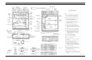
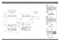
The Dual Format MDX Mobile Radio assembly con-
tains the following circuit boards and assemblies:
•
Power Amplifier Board 19C851822G1
•
RF Board 19D902123G22
•
System Board 19D901891G2
•
Audio/Logic Board 19D903963G1
•
Audio Amplifier Board 19D904025G2
•
Front Cap Assembly 19D904151G1
The circuit boards are all mounted on a main casting to
provide easy access for servicing. Interconnect plugs are used
to connect the boards to eliminate pinched wires and other
wiring problems.
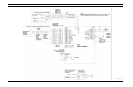
RF BOARD
The RF Board includes the programmable frequency syn-
thesizer, transmitter exciter, receiver front end and IF circuitry.
Synthesizer
The synthesizer circuit generates all transmit and receive
RF frequencies. The synthesizer frequency is controlled by the
microprocessor located on the Audio/Logic Board. Frequency
stability is maintained by a temperature compensated reference
oscillator module. Transmit audio is processed on the
Audio/Logic Board and applied to the synthesizer to modulate
the VCO and TCXO. The buffered VCO output drives both the
transmitter exciter and the receiver mixer.
Transmitter
The transmitter consists of a fixed-tuned exciter module,
a PA module and a power control circuit. The PA module
provides RF output to drive the antenna. The power control
circuit controls the PA module to maintain a constant output
power across the band. The RF output level is internally adjust-
able for rated power. Thermistors in the control circuit protect
the PA from overheating by reducing the power output level.
Receiver
The dual conversion receiver circuit consists of a front end
section, 45.3 MHz first IF, a 455 kHz second IF, and FM
detector. All audio processing and squelch functions are ac-
complished on the Audio Board.
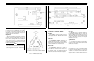
POWER AMPLIFIER BOARD
The PA board (19C851822G1) amplifies the RF board
output then connects it back to the RF board where it is coupled
through a PIN diode antenna switch, the low-pass filter and the
directional coupler to provide 25 watts power output at the
antenna connector.
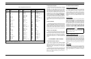
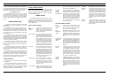
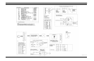
67.0 71.9 74.4 77.0 79.7 82.5 85.4 88.5 91.5 94.8 97.4
100.0 103.5 107.2 110.9 114.8 118.8 123.0 127.3 131.8 136.5 141.3
146.2 151.4 156.7 162.2 167.9 173.8 179.9 186.2 192.8 203.5 210.7
1. Do not use 179.9 Hz or 118.8 Hz in areas served by 60 Hz power distribution systems (or 100.0 Hz or 151.4 Hz in areas supplied with 50Hz power). Hum
modulation of co-channel stations may "false" Channel Guard decoders.
2. Do not use adjacent Channel Guard tone frequencies in systems employing multiple Channel Guard tones. Avoid same-areas co-channel use of adjacent
Channel Guard tones whenever possible. As stated in EIA Standard RS-220, there is a possibility of decoder falsing.
3. To minimize receiver turn-on time delay, especially in system using Channel Guard repeaters or receiver voting, choose the highest usable Channel Guard
tone frequency. Do not use tones below 100 Hz when it is necessary to meet the receiver response time requirements of EIA Standard RS-220.
Table 1 - Standard Tone Frequencies (Hz)
SPECIFICATIONS*
GENERAL
Regulatory Approval
FCC (United States) AXATR-311-A2
DOC (Canada) TR-311
Operating Voltage 13.8 Volts ±20%
Battery Drain
Receiver (13.8 Vdc)
Off 0.01 Amperes (maximum)
Squelched 0.75 Amperes (maximum)
Unsquelched 2.0 Amperes (maximum at 10 Watts audio,
External Speaker)
Transmitter (13.8 Vdc) 11 Amperes (maximum at 25 Watts RF)
Channel Spacing 25 kHz (12.5 kHz NPSPAC)
Frequency Stability ±1.5 PPM (±0.00015%)
Temperature Range -30C to +60C (-22F to +140F)
Dimensions (H x W x D)
(Less Accessories)
Height 5.3 cm (2.1 inches)
Width 18.2 cm (7.2 inches)
Depth 24.0 cm (9.5 inches)
Weight 3.0 kg (6.6 pounds)
Antenna Impedance 50 Ohms
TRANSMITTER
Frequency Range 806.0125-824.9875 MHz
Output Power 25 Watts (Intermittent duty cycle; EIA 20%)
Audio Sensitivity 125 mVrms (typical)
Spurious and Harmonics <-16 dBm
Audio Distortion 5% maximum
Modulation Limiting +5 kHz maximum (4 kHz max 821.000 - 824.9875 and
866.000 - 869.9875 MHz)
FM Hum and Noise -45 dB
Audio Frequency Response Within +1, -3 dB of a 6 dB/octave pre-emphasis curve
Per EIA Standards from 300-3000 Hz
RECEIVER
Frequency Range 851.0125-869.9875 MHz
Acceptable Frequency Displacement ±2.5 kHz minimum
Sensitivity (12 dB SINAD) -113 dBm minimum
Spurious Response 70 dB minimum
Adjacent Channel Selectivity 68 dB minimum at ±25.0 kHz
Intermodulation Distortion 65 dB minimum
Audio Frequency Response Within +2, -8dB of a 6 dB/octave de-emphasis curve
from 300 -2700 Hz
Audio Output 10 Watts (External Speaker); 4 Watts (Internal Speaker)
Audio Distortion 5% maximum at 1 kHz
*
These specifications are intended primarily for use by service personnel. Refer to the appropriate Specification Sheet
for complete specifications.
LBI-38848D
2