


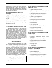
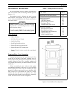
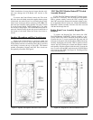
RF Board Access
Holes are located in the RF Board shield for alignment
of the Reference Oscillator (U3), Modulation Balance pot
(R18), VCO Modulation pot (R19), 2nd Local Oscillator
Adjustment (T1), and the Quadrature Detector Adjustment
(T2). To align these items, shield removal is not necessary.
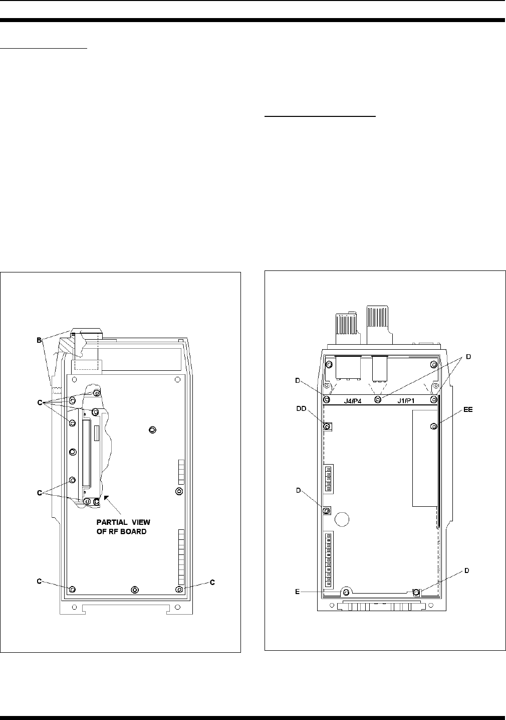
If removal of the RF Board from the case is necessary,
first remove the UDC antenna jack and the top RF antenna
jack with appropriate spanner wrenches. Next, remove the
five (5) Torx screws (B) that secure the shield then lift and
remove the shield. Remove the two (2) remaining Torx
screws (C) near the Power Amplifier Module. The RF Board
and eggcrate casting can now be lifted from the Rear Cover
to gain access to the chip component side of the board. If
necessary, the RF Board can be separated from the eggcrate
casting. Remove the two (2) Torx screws that secure the
Power Amplifier Module and remove the four (4) screws on
the chip component side of the board that secure it to the
casting.
Reassemble the unit in reverse order. Observe screw
lengths.
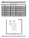
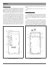
Control Board Access
To gain partial access to the Control Board, remove the
five (5) screws (D) securing the shield and board. An earlier
Front Cover Assembly has an additional screw located just
below connectors J4/P4 (DD). See Figure 8. Remove the
shield.
Many of the test points on the Control Board are acces-
sible at this point; however, the Front Cover Assembly
should not be powered-up without first reinstalling the
screw into the lower right-hand hole to ground the board.
Also, the three (3) screws securing the top flex connectors
need to be reinstalled for good flex connections. USE CAU-
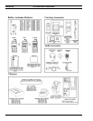
Figure 8 - Control Board Access
Figure 7 - RF Board Access
LBI-38378D
14