because it contains many frequencies simulta-
neously, just like real voice or instrument pro-
gram. The signal contains more energy at
extremely high and low frequencies than typi-
cal actual program, adding an extra margin of
reliability. The test combines not only the overall
long-term average or continuous levelwhich
our ear interprets as loudnessbut also short-
duration peaks which are many times higher
than the average, just like actual program. The
long-term average level stresses the speaker
thermally (heat). The instantaneous peaks test
mechanical reliability (cone excursion). Note
that the sine-wave test signals sometimes
used have a much less demanding peak value
relative to their average level. In actual use,
long-term average levels exist from several
seconds on up. We test for several hours,
adding another extra level of reliability.
Specifically, the TL18-1 is designed to with-
stand the power test described in EIA Standard
RS-426A. The EIA test spectrum is applied for
eight hours. The spectrum is obtained by filter-
ing white noise (a particular type of random
noise with equal energy per bandwidth). The
filter applies a 6-dB-per-octave slope below
40 Hz and above 318 Hz. When measured with
a one-third-octave constant-percentage ana-
lyzer, this filter produces a spectrum whose
3-dB-down points are at 100 Hz and 1,200 Hz
with a 3-dB-per-octave slope above 1,200 Hz.
This shaped signal is fed to the power amplifier
with the continuous power set to provide 400
watts into the 6.8-ohm EIA equivalent imped-
ance (48.2 volts rms).
Amplifier clipping sets instantaneous peaks at
6 dB above the continuous power, or 1,200
watts peak (96.4 volts peak). This procedure
provides a rigorous test of both thermal and
mechanical failure modes.
STEP-DOWN
Step-down is a method of extending the low-
frequency response by increasing the power
input to the system instead of the enclosure
volume. In step-down mode, the enclosure is
tuned at a lower-than-normal frequency. This
increases the output at the new tuning fre-
quency and reduces the output at the original
tuning frequency. This smoothly falling ampli-
tude response can be equalized to obtain a
new 3-dB-down point in the region of 0.7 that
of the original. To obtain a similar response
without step-down would require an enclo-
sure with at least twice the volume.
Step-down can be instigated by using the
supplied port cover. Remove the metal grille.
Install the plastic port cover and staple it in
place. Replace the metal grille. The enclosure
tuning will be lowered from 40 to 28 Hz.
If an appropriate low-frequency boost-and-
cut equalization is applied, the normal f
3
of 40
Hz is reduced to 28 Hz. It is suggested that the
Electro-Voice XEQ-2 or XEQ-3 active cross-
over be used to provide the required equaliza-
tion. The suggested equalization is an
underdamped second-order high-pass filter
tuned to 29 Hz with a Q of 2. This provides a
boost of 6 dB at the tuning frequency and a
12-dB-per-octave roll-off below. This filter is
directly available on the XEQ-2 or can be
generated in the XEQ-3 by using the optional
EB29/35 EQ module.
SUBPASSBAND SPEAKER PROTECTION
Below the enclosure tuning frequency, cone
excursion increases rapidly. Since acoustic
output is also falling rapidly, there is no utility in
driving the system with signals much below
tuning frequency. While such signals may be in
the program material, they are often extrane-
ous, such as a dropped microphone. The step-
down equalization described in the Step-Down
section provides the required protection. If
step-down mode is not used, the Electro-Voice
EX-24, XEQ-2 and XEQ-3 electronic cross-
over/equalizers can also provide subpassband
protection. The 3-dB-down points are 30 Hz
(EX-24 and XEQ-2) and 16 Hz or 32 Hz
(XEQ-3).
Other high-pass filters are available and
1
/3-octave equalizers can also be effective at
providing the required protection.
USE IN MULTIPLES
TL systems may be stacked for greater acous-
tic output and a narrower beamwidth.
(It is assumed that all cones are operating in
unison or in phase.)
At relatively low frequencies, below about 150
Hz for typical TL series dimensions, stacking
produces additional acoustic output without
altering dispersion. When a common signal is
applied, a 6-dB increase in maximum acoustic
output occurs. The cones mutually couple
and act as one cone with twice the area
(therefore twice the efficiency) and twice the
power capacity. The additional cone area pro-
vides
3 dB more output and the additional power
capacity accounts for the remaining
3 dB.
Specifically, mutual coupling occurs at fre-
quencies whose wavelengths are longer than
one-quarter the center-to-center distance be-
tween the cones. The highest frequency at
which mutual coupling occurs is calculated
from the following equation:
f ≅
3,000
,
D
MAX
where D
MAX
(inches) is the distance between
the cones, and f (Hz) is the highest frequency
at which coupling occurs. When D
MAX
is greater
than one-quarter wavelength, which would
occur if two TL18-1s were widely spaced, or
at frequencies much above f even when closely
spaced, the increase in acoustic output is
limited to the 3-dB power-handling increase.
At frequencies above the mutual coupling limit,
f, stacking alters dispersion and increases on-
axis sensitivity. In the 500-to-800-Hz range, a
common crossover frequency for two-way
sound reinforcement systems, two nearly
adjacent cones have a coverage angle about
half that of either cone alone. This is useful, for
example, in more closely matching the typical
40° vertical dispersion of a high-frequency
horn. (At frequencies much above 800 Hz, the
concept of a halved coverage angle no longer
applies, since the side lobes, which result from
enclosure.
The TL18-1s large pumping capability and
40-Hz 3-dB-down point make it appropriate as
a subwoofer for contemporary music play-
back and sound reinforcement. In the step-
down mode, the TL18-1s 28-Hz f
3
makes it
appropriate for very-low-frequency synthe-
sized effects, down-tuned bass guitars, and
approaches the depths of the symphony or-
chestra and pipe organ. (See Step-Down sec-
tion.)
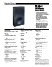
The enclosure is finished in black with a match-
ing metal grille. Connections are made via
barrier strip (#10) recessed into the back of the
enclosure on a durable molded connector panel.
The enclosure is constructed from ProWood
TM
,
a composite structural material which is easily
refinished. ProWood is made of selectively
oriented hardwood strands strongly bonded
together within a phenolic resin matrix. The
surface is a proprietary vinyl laminate, espe-
cially formulated for Electro-Voice, which can
be painted or stained to match any decorative
environment (see Finishing ProWood section).
The TL series is suited for any installation
where high-quality sound is required. The
weather-resistant finish makes these systems
suitable for both indoor and covered outdoor
applications including stadiums, auditoriums
and churches. The enclosures may be stacked
for greater output capability or for a narrower
beamwidth (see Use in Multiples section).
FREQUENCY RESPONSE
The TL18-1s axial frequency response was
measured in Electro-Voices large anechoic
chamber at a distance of 10 feet with a swept
sine-wave input of 4 volts. Figure 1 has been
averaged and corrected for 1 watt/1 meter.
DIRECTIVITY
The directional characteristics of the TL18-1
were measured in Electro-Voices large ane-
choic chamber. The test signal was one-third-
octave filtered pink noise at the frequencies
indicated. A full spherical measurement sys-
tem was used, which is compatible with the
AcoustaCADD
TM
computer-aided design pro-
gram. All directional information was measured
at 20 feet.
Figure 2 illustrates the horizontal and vertical
polar responses.
Figure 3 shows the horizontal and vertical
beamwidths. Beamwidth is the angle at which
the horizontal and vertical polar responses
have decreased in level by 6 dB when com-
pared to the axial frequency response.
Figure 4 illustrates the total directivity of the
TL18-1. The directivity factor R
θ
(Q) is the
relative value, at a point, of the TL18-1
when compared to an ideal spherical response.
The directivity index, D
i
, is calculated by
D
i
= 10 log R
θ
.
POWER HANDLING CAPACITY
To our knowledge Electro-Voice was the first
U.S. manufacturer to develop and publish a
power test closely related to real-life condi-
tions. A random noise input signal is used


