


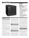

MTH-1 Biampable, Mid/High Coaxial Module Speaker System
MTH-1 Biampable, Mid/High Coaxial Module Spealer System
2
speaker system. For the MTH-1, this is 700
to 2,800 watts.
The caution cannot be made strongly
enough, however, that this arrangement
is only for experts or those who can disci-
pline themselves against “pushing” the
system for ever-higher sound levels and
who can avoid “accidents” such as cata-
strophic feedback or dropped micro-
phones.
2. A more conservative, “normal” ampli-
fier size, which will produce audible results
nearly equal to those of the “expert” recom-
mendation, is 1.0 to 1.4 times the long-term
average noise power rating of the speaker.
For the MTH-1, this is 350 to 490 watts.
3. To be very conservative, one can use an
amplifier rated at 0.5 to 0.7 times the long-
term average noise power rating of the loud-
speaker. For the MTH-1, this is 175 to 245
watts.
Request P.A. Bible Addition No. Two
(“Power- Handling Capacity”) for more
background on these recommendations.
Speaker Protection
A self-resetting high-frequency protection
circuit, Electro-Voice's PRO
™
circuit, is in-
cluded in the MTH-1 to prevent against ac-
cidental overdrive and improve reliability. If
the input power to the high-frequency driver
exceeds the nominal rating, the protection
circuit is activated and reduces the power
delivered to the driver. The system will re-
main in this mode of operation until the in-
put power is reduced to a safe level.
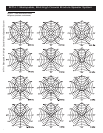
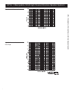
Frequency Response
The MTH-1’s axial frequency response was
measured in Electro-Voice’s large anechoic
chamber at a distance of 3 meters (10 feet)
with a swept sine-wave input. Figure 2 has
been averaged and corrected for 1 watt at 1
meter.
Enclosure Construction
Intended to be used as a portable speaker sys-
tem, the MTH-1 is ruggedly constructed of
3/4-inch, void-free plywood. All joints are
dado cut, and the cabinet is finished with a
densely-woven, abuse-resistant carpet that is
both attractive and highly durable. A full-
length steel grille protects the system from
damage. Large, heavy-duty metal corner pro-
tectors, firmly secured rubber feet, and re-
cessed handles complete the picture, ensur-
ing that the MTH-1 speaker system is ide-
ally suited for a long and reliable life on the
road.
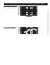
MTH-1 Connections
The MTH-1 is equipped with two paralleled
Neutrik Speakon
®
NL4MD-V connectors,
selected for their ability to reliably deliver to
the speaker components the high currents
delivered by high-wattage power amplifiers.
The NL4FC is a four-pin mating connector
for the NL4MD-V, and Figure 5 shows how
the usual two-conductor speaker cable
should be wired to pins 1+ and 1– of the con-
nector. Two typical connectors at the power
amplifier end of the cable are shown: banana
and 1/4-inch phone plugs. (The banana plug
provides the more reliable connection.)
Full-range pin arrangements are:
1– = IN (–)
1+ = IN (+)
2– = Not Used
2+ = Not Used
Biamp pin arrangements are:
1– = MB (–)
1+ = MB (+)
2– = HF (–)
2+ = HF (+)
To find your local Neutrik dealer, contact:
Neutrik USA, Inc.
195-S3 Lehigh Ave.
Lakewood, NJ 08701
908/901-9488
Service
In the unlikely event the MTH-1 requires
service, the woofers can be replaced or
serviced from the front. A service data sheet
is available from Electro-Voice.
Power-Handling
The MTH-1 comes in full-range mode. This
switchable to biamp mode. In biamp mode,
the long-term average power-handling ca-
pacity is as follows:
Mid Frequency: 300 watts
High Frequency: 60 watts
Electro-Voice components and systems are
manufactured to exacting standards, ensur-
ing they will hold up, not only through the
most rigorous of power tests, but also through
continued use in arduous, real-life conditions.
The EIA Loudspeaker Power Rating Full
Range (EIA RS-426-A 1980) uses a noise
spectrum which mimics typical music and
tests the thermal and mechanical capabili-
ties of the components. Electro-Voice will
support relevant additional standards as and
when they become available. Extreme, in-
house power tests, which push the perfor-
mance boundaries of the woofers, are also
performed and passed to ensure years of
trouble-free service.
Specifically, the MTL-1 passes EIA RS-426-
A 1980 with the following values:
R
SR
= 7.6 (1.15 x R
E
)
P
E(MAX)
= 350 watts
Test voltage = 51.5 volts rms,
103.1 volts peak
The “peak” power-handling capacity of a sys-
tem is determined by the peak test voltage
amount. For the MTH-1, a 103.1-volt peak
test voltage translates into 1,400-watts short-
term peak power-handling capacity. This is
the equivalent of four times the “average”
power-handling capacity, and is a peak that
can be sustained for only a few milliseconds.
However, this sort of short duration peak is
very typical in speech and music. Provided
the amplifier can reproduce the signal accu-
rately, without clipping, the system will also
perform accurately and reliably, even at these
levels.
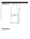
Suspending MTH-1 Enclosures
The MTL-1 has been developed in conjunc-
tion with the HSMT-1 series of hanging hard-
ware. The HSMT-1 kit allows the MTH-1
to be hung safely in a variety of orientations.
The combination of the HSMT-1 kit and
MTL-1 enclosure has been certified by an
independent structural engineer to be safe
and secure. Each HSMT-1 kit consists of a
tube, two brackets, two eyebolys and the nec-
essary fasteners. The installer must assemble
the HSMT-1 kit by first drilling two holes in