


4 – SMS3
SMS3 – 5
4. INSTALLATION
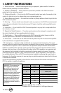
The special hexagonal shape of the cabinet makes it possible to
position the speaker in various ways, as shown in the gure. The
logo plate on the front protective grille can be rotated to adapt
it to the position of the speaker. The speaker body has four M6
threaded inserts, one each on the top and bottom and two on the
back, used for attaching accessories for installing the speaker in
different ways.
SMS3 (SMS3W) speakers are supplied with a black (white)
ball joint support for wall mounting.
WARNING: Consult a professional rigger or structural
engineer prior to suspending loudspeakers from a
structure not intended for that use. Always know the
working load limit of the structure supporting
the loudspeaker array. Always make sure
that the rigging hardware minimum rating is
at least ve times the actual load.
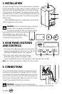
5. REAR PANEL FEATURES
AND CONTROLS
1.
This rotary control selects the power tap for the internal
constant voltage transformer. Choices are 1W, 2.5W, 5W,
10W, 20W, and BYPASS (used for 4 ohm operation).
2. This rotary control selects the constant voltage
distributed system in which the speaker is used.
Choices are BYPASS (used for 4 ohm operation), 0 (Off), 25V, 50V, 70V and 100V.
Note: Use a slot-head screwdriver to adjust the rotary controls.
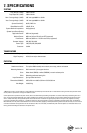
6. CONNECTIONS
The spring-loaded speaker terminals are designed to accept
bare wire, up to a maximum of 18 gauge. Strip 1/4’’ (6 mm)
of insulation off the end of the speaker wire, press in the tab,
and insert the bare wire into the hole. When you release the
tab, the wire is locked in place. Make sure there are no stray
strands of wire outside the terminal connection.
WARNING: To prevent the risk of electrical shock,
always fit the protective cover over the terminals after completing the connections.
+
-
SMS3
Ω
Ω