


25
8.5 Amplifier Service
WARNING: Disconnect the ac mains cable before doing this procedure.
ATTENTION: Déconnectez le cordon du secteur avant d'entamer cette procédure.
ATTENZIONE: Prima di procedere con questa operazione, disconnettere il cavo
d'alimentazione AC.
PRECAUCION: Desconecte el cable de alimentación antes de realizar este proceso.
WARNUNG: Ziehen Sie den Netzstecker aus der Steckdose, bevor Sie mit dieser Prozedur beginnen.
Faulty electronics are serviced by replacing the entire amplifier module.
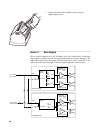
8.5.1 Amplifier Modules
There are two types of NT amplifier modules:
one for the NT full-range models and one for the subwoofer.
1.Full-range: Input, DSP, 1000 W @ 4 ohm LF amplifier, 500 W @ 4 ohm
HF amplifier, and power supply.
2.Subwoofer: Input, DSP, two 1000 W @ 4 ohm amplifiers, and power supply.
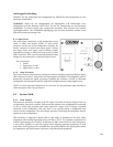
For the NT full-range models (NT2x & NT5x), each amplifier module has the DSP settings
for all models stored in on-board memory. The active settings are determined by on-board
dip switch settings. Thus,amplifier modules for the full-range models are interchangeable
by simply resetting the dip switches for that particular model.
8.5.2 NT Amplifier Replacement Modules and Dip Switch Settings
An amplifier replacement module consists of the power amplifiers, DSP board, power
supply, connectors, and indicators; all pre-mounted on the amplifier panel.
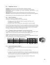
Amplifier Module Replacement Part Numbers & Dip Switch Settings
NOTE: If the incorrect DIP switch position is used, poor/incorrect performance will result,
at best sounding bad, at worst causing equipment failure.
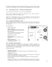
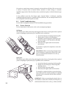
8.5.3 Replacing the Amplifier Module
1. Remove the amplifier module from the other side of the enclosure by removing its12
retaining screws.
2. Disconnect the quick release connector for the transducer cabling.
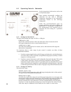
3. Configure the replacement amplifier for the NT model by setting the dip switch. See
the chart in Section 8.5.2 for the correct settings. The dip switch is located behind the
input receptacles on the backside of the amplifier module.
4. Once the dip switch is programmed, connect the transducer cabling to the
replacement module.
NT Model # 115 V Module
NT26
NT29
NT56
NT59
NTS22
#0016088
#0016088
#0016088
#0016088
#0016090
230 V Module
Dip Switch Settings
#0016584
#0016584
#0016584
#0016584
#0016585
Off
Off
Off
Off
Off
Off
Off
Off
Off
On
Off
On
On
Off
Off
Off
On
Off
On
Off
123
4
NOTE: Off is up, On is down.