


52 EAGLE - EVR-150 Installation and Operation Instructions
Appendix D - Wiring for EAGLE GPS models
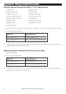
Wiring for Eagle GPS models with NDC-4, 119-31, Adapter Cable:
FishElite 480 FishElite 500c
FishElite 502c iGPS FishElite 640c
FishElite 642c iGPS SeaCharter 500c DF
SeaCharter 502c DF iGPS SeaCharter 640c DF
SeaCharter 642c DF iGPS IntelliMap 480
IntelliMap 500c IntelliMap 502c iGPS
IntelliMap 640c IntelliMap 642c iGPS
Cuda 250 S/Map
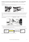
1. Remove diode and resistor (installed at end of cable) – refer to next page for instructions
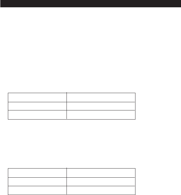
2. Connect wires as follows:
EVR-150 Eagle GPS Unit
Yellow (NMEA IN +) Yellow (NMEA OUT)
Green (NMEA IN -) Drain – Bare Stranded (Ground)
3. Configure the COM port on the connected EAGLE GPS unit. Refer to the documentation
supplied with your EAGLE GPS model.
Wiring to Eagle GPS model with PC21X, 99-56, Power Cable:
SeaCharter 480DF
1. Connect wires as follows:
EVR-150 Eagle GPS Unit
Yellow (NMEA IN +) Yellow (NMEA OUT)
Green (NMEA IN -) Drain – Bare Stranded (Ground)
2. Configure the COM port on the connected EAGLE GPS unit. Refer to the documentation
supplied with your EAGLE GPS model.