


Operation
•
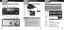
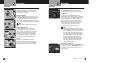
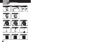
Selecting a Channel
Rotate the Channel knob clockwise
until desired channel is displayed.
Channel 9/NOR/Channel 19
Set CH 9 to obtain instant access
to the emergency channel.
Set
NOR position to use the channel knob
to choose any of the 40 channels.
Set
CH 19 to obtain instant access to
the information and calling channel.
CB/PA
In the CB position, the PA function is disabled
and the unit will transmit and receive on the
selected channel. The
PA function should not
be used unless a PA speaker is connected. In the
PA position, the transmit function is disabled and
the microphone output will go only to the PA speaker.
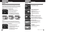
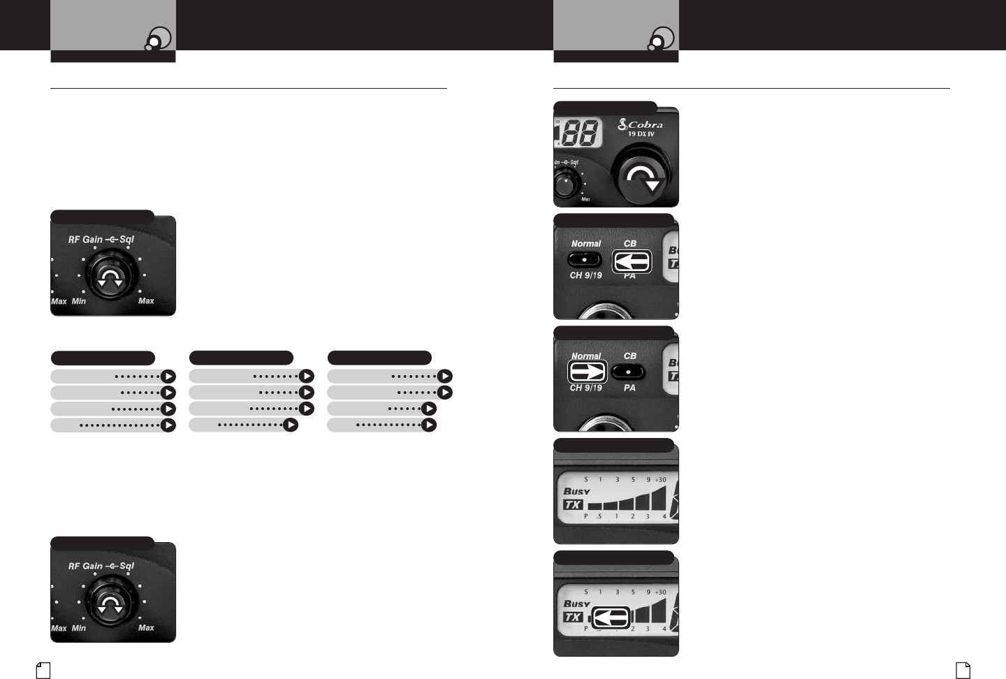
S/RF Power Meter
Shows relative transmitter RF output power
and input signal strength when receiving.
The Liquid Cr
ystal Display (LCD) segments
increase with signal strength.
TX Indicator
The TX Indicator will light when in the
transmit mode. “Busy” will appear when
there is an incoming signal.
7
Nothing comes close to a Cobra
®
6
English
Operation
•
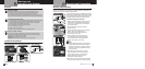
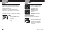
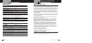
Squelch
This control is used to cut off or eliminate receiver background noise in the absence
of an incoming signal. Adjust until the receiver noise disappears. This will require the
incoming signal to be slightly stronger than average receiver noise. Further clockwise
rotation will increase the threshold level which a signal must overcome in order to be
heard. Only strong signals will be heard at a maximum clockwise setting.
Squelch is the “control gate” for incoming signals.
To squelch your radio:
1.
Full clockwise rotation closes the gate,
allowing only ver
y strong signals to enter.
2. Full counterclockwise rotation opens
the “gate,” allowing all signals in.
3. To achieve the Desired Squelch Setting (DSS),
turn the Squelch control counterclockwise until
you hear noise. Now turn the control clockwise
just until the noise stops. This is the DSS setting.
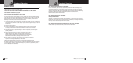
RF Gain
This control is used to adjust receiver sensitivity
. Maximum sensitivity allows
weak signals to be received. However, very strong signals (such as from a nearby
transmitter) can cause distortion at that setting. Adjust until the distortion disappears.
Reducing the receiver’s RF Gain eliminates distortion from very strong incoming signals.
To set RF Gain:
1.
Full counterclockwise rotation minimizes
gain for maximum distortion control.
2. To achieve the desired level of distortion control,
turn the RF Gain knob counterclockwise until
the distortion is eliminated.
3. After moving away from the strong signal,
turn the RF Gain knob fully clockwise to
receive all possible signals.
C
hannel Selector Knob
Notice
Secondary Icons
Caution Warning
Installation
Customer
Assistance
Channel 9/NOR/Channel 19 Button
Intro Operation Customer
Assistance
Warranty
Notice
Main Icons
Secondary Icons
Caution Warning
Installation
Customer
Assistance
CB/PA Button
Intro Operation Customer
Assistance
Warranty
Notice
M
ain Icons
Secondary Icons
Caution Warning
Installation
Customer
Assistance
S/RF Power Meter
TX Indicator
Intro Operation Customer
Assistance
Warranty
Notice
Main Icons
Secondary Icons
Caution Warning
Installation
Customer
Assistance
Intro Operation Customer
Assistance
Warranty
Notice
S
econdary Icons
Caution Warning
Installation
Customer
Assistance
Operating Your Mobile Radio
OperationOperation
Intro Operation Customer
Assistance
Warranty
Notice
S
econdary Icons
Caution Warning
Installation
Customer
Assistance
Operating Your Mobile Radio
A
djust Squelch/RF Gain Knob
Intro Operation Customer
Assistance
Warranty
Notice
M
ain Icons
Secondary Icons
Caution Warning
Installation
Customer
Assistance
Adjust Squelch/RF Gain Knob
Intro Operation Customer
Assistance
Warranty
Notice
Main Icons
Secondary Icons
Caution Warning
Installation
Customer
Assistance
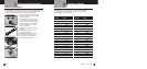
Gate Closed
Strong Signals
Medium Signals
Weak Signals
Noise
Gate Open
Strong Signals
Medium Signals
Weak Signals
Noise
Desired Squelc
h Setting (DSS)
Strong Signals
Medium Signals
Weak Signals
Noise