


4
5
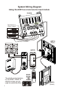
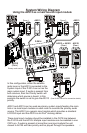
System Wiring Diagram
Using the A0315 as a local source input module
System Wiring Diagram
Using the A0315 as a main source input module
A0315
(Rear)
A0315
(Rear)
A0315
(Front)
1 4 5 Aud trib t n od l CAT io Dis u io M u e
e )(Rquired
w
Po er
t
)(Op ional
S atut s
System
s mSyte
n
Iput
Local
Input
Zo 1
ne
Zo 2
ne
Zo 3
ne
Zo 4ne
Expansion
Otuput
Local
Priority
Sigaln
L R
Em t ersi t
OPR
CHANNEL
TM
VISION
CHANNEL
VISION
TM
RI
x
TM
CHN NEL ISI ON
A
V
MdeP 201o l -
4
A0125
P-2014
A0501,
A0502,
OR
A0505
The shuttle control buttons
on the A0501, A0502, &
A0505 remotes can be
used to control the iPod.
Tape Monitor or
Room 2 output
(Optional) IR emitters
Sat radio
DVD player
CD player
Receiver
Amp-Link
Channel Vision
R
L/S
Line Out
TM
IICH A
NN EL VSO
N
S
O
U
R
C
E
ZN
OE
POWER
TMU E
VOL
1
2
3
4
O
MDEL
0A501
WER
PO
Source
CHANNEL VISI ON
Pwr
Amp-Link
Channel Vision
R
L/S
Line Out
Amp-Link
Channel Vision
R
L/S
Line Out
Amp-Link
Channel Vision
R
L/S
Line Out
1 4 AT5 udi i b M dul C A o D stri ution o e
(Reuirdq e)
Pwroe
(Otioap nl)
S statu
ys emS t
System
Input
Local
Input
Zne 1o
Zne 2o
Zne 3o Zone 4
Epnioxasn
Outptu
Locl
a
Priority
S g l
ina
L R
Emittr
e s
PRO
H NE
C AN L
MT
V IONIS
H NE
C AN L
V IONIS
MT
IR
x
MT
CH AN NELVI SI ON
e 14Modl P-20
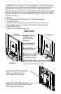
A0301 and A0315 can be used as primary system inputs feeding the main
hub or as local input modules in each room to override the primary audio
source. The A0301 is a generic input module which provides a standard
®
L/R RCA input and the A0315 is an iPod docking station.
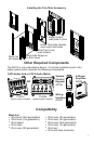
These local input modules should be installed in the CAT5 line between
the P-2014 and the A0125. Multiple input modules can be installed in one
CAT5 run. If audio is present at more than one input module the unit
closest to A0125 will take priority and be played through the speakers.
In this configuration, either the satellite
radio tuner or the A0315 connected to the
System Input of the P-2014 can act as the
main system input. If audio is present from
both sources, then the Priority switch will
determine which source is heard. In this
example the switch is set to give the A0313
priority.
Source
CHANNEL V ISION
Pwr
Source
CHANNEL V ISION
Pwr
Room 1 Room 3
A0313A0313
P-2014
A0313 or A0301
(Rear)
A0125
(Rear)
A0302
OUT
OUT
IN
IN
Secondary audio source
Primary audio source
(See A0125 manual for connection details)
Sat radio