


Modelos NS219000, NS289100, NS289500 y NS349000
5-Sp
4. Presione el
empujador
con el
enganche
para desen-
ganchar al
empujador.
Asegúrese de que la cabeza del
último clavo esté debajo de la
cabeza del empujador.
CÓMO DESCARGAR LA CLAVADORA
1. Siempre descargue todos los
sujetadores antes de retirar la
herramienta de funcionamiento. La
acción de descargar es lo contrario
a la de cargar, con la excepción que
siempre debe desconectarse la
manguera de aire antes de
descargar.
2. Jale el
mecanismo
del empu-
jador de
clavos hasta
que el
empujador
se engrane
con el
enganche
del cargador.
3. Sostenga la
herramienta
hacia arriba
para que los
clavos se
deslicen
para atrás
hacia la
ranura del
cargador.
4. Presione el
empujador
con el
enganche
para desen−
ganchar al
empujador
una vez que se hayan retirado todos
los clavos.
CÓMO AJUSTAR LA PENETRACIÓN DEL
CLAVO
Las clavadoras NS219000, NS289100,
NS289500 y NS349000 tienen una
característica de profundidad de
accionamiento ajustable. Esto permite
que el usuario determine qué tan
profundo se va a introducir un clavo en la
superficie de trabajo.
1. Ajuste la presión de operación a una
presión que accionará uniformemente
a los sujetadores. No exceda la
máxima presión de operación de la
clavadora de 8,27 bar.
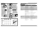
2. Para ajustar la profundidad de
accionamiento, afloje el perno de 4
mm que está encima de la nariz. Para
aumentar la profundidad, presione el
elemento de contacto de trabajo
(WCE), hacia la nariz, tanto como lo
desee. Vuelva a ajustar el perno. Para
disminuir la profundidad, retire el
WCE tanto como desee. Vuelva a
ajustar el perno.
3. Asegúrese
de que el
gatillo y el
elemento
de contacto
de trabajo
(WCE) se
muevan
fácilmente
hacia arriba
y hacia
abajo sin pegarse o atracarse luego
de cada ajuste.
ANTI DISPARO SIN CARGA
La NS219000 está equipada con una
característica de anti disparo sin carga. Esto
evita que se presione el WCE cuando sólo
queden pocos clavos. Simplemente cargue
nuevos clavos a continuación de los que
quedan, para continuar disparando.
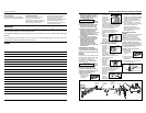
CÓMO AJUSTAR LA DIRECCIÓN
DEL ESCAPE
Las clavadoras
NS219000,
NS289100,
NS289500 y
NS349000
vienen con un
deflector de
escape de dirección ajustable. Esto está
diseñado para que el usuario pueda
cambiar la dirección del escape. Con la
llave de 5 mm que se proporciona,
afloje el tornillo del deflector; luego
gire el deflector en la dirección deseada
y vuelva a ajustar el tornillo.
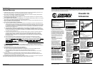
CÓMO DESATASCAR LA CLAVADORA
1. Desconecte la
clavadora del
abaste-
cimiento de
aire.
2. Retire todos
los clavos del
cargador (ver
Cómo cargar
o Cómo
descargar). Si
se ignora
este paso, los
clavos
saldrán
disparados
por la parte
frontal de la
herramienta.
3. Inserte un
desar-
mador en
la nariz de
la he-
rramienta.
Empuje la
cuchilla
del accionador para soltar el clavo
atracado.
4. Sujete el
clavo
atracado
con unos
alicates, y
retírelo.
Servicio Técnico
Si desea hacer alguna pregunta
referente a la reparación u operación de
las clavadoras, sírvase llamar a nuestro
número especial, 1-800-543-6400. Si
llama desde Ohio o fuera de los Estados
Unidos continentales, comuníquese con
nosotros al 1-513-3678-1182.
Clavos et Repuestos
Use
solamente
sujetadores Campbell Hausfeld originales
(o su equivalente) - (vea la información
sobre intercambio de sujetadores). Use
solamente partes de repuesto Campbell
Hausfeld originales. Nunca substituya las
partes. No use partes modificadas o
partes que no den un rendimiento
equivalente al equipo original. El
rendimiento de las herramientas, la
seguridad y la duración pueden verse
reducidos. Cuando ordene partes de
repuesto o sujetadores, especifique el
número de la parte.
Para reparar la clavadora
Las reparaciones de la clavadora las
debe hacer SOLAMENTE un técnico
calificado que tenga experiencia.
Para colocarle los sellos
Cada vez que repare una clavadora
deberá limpiarle y lubricarle las partes
internas. Le recomendamos que use
Parker O-lube o un lubricante
equivalente en todos los anillos en O. A
cada anillo en O se le debe dar un baño
de lubricante para anillos antes de
instalarlos. Igualmente, deberá ponerle
un poco de aceite a todas las piezas
que se mueven y muñones. Finalmente,
después de haberla ensamblado y antes
de probar la herramienta deberá
ponerle unas cuantas gotas de aceite
sin detergente 30W u otro aceite
similar, en las líneas de aire.
!
ADVERTENCIA
Rotate
Gire
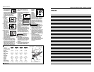
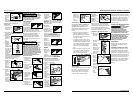
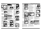
LOADING THE NAILER
1. Always connect the tool to the air
supply before loading fasteners.
2. Pull nail
pusher
mechanism
back until
pusher
engages
with
magazine
latch.
3. Load strips
of fasteners
into the
magazine
slot. Make
sure that
the nails
are placed
into tool at the proper orientation.
4. Squeeze the
pusher and
the latch
together to
unlatch
pusher.
Make sure
the head of the last nail is under the
head of the pusher.
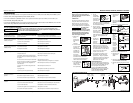
UNLOADING THE NAILER
1. Always unload all fasteners before
removing tool from service.
Unloading is the reverse of loading,
except always disconnect the air
hose before unloading.
2. Pull nail
pusher
mechanism
back until
pusher
engages
with
magazine
latch.
3. Hold tool
upright so
nails will
slide
backwards
toward
magazine
slot.
Nail pusher
mechanism
Latch
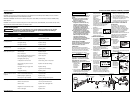
4. Carefully
place no-
mar tip
over the
end of
work
contact
element.
Position
tip onto
WCE
making certain serrated gooves on
each piece are in line and fit snugly
together.
5. Position
retaining
ring on no-
mar tip and
press firmly
in place.
6. Check
that the
WCE and
trigger
move up
and down
freely
without
sticking or
binding.
Operational Modes
Always know the
operational mode
of the nailer before using. Failure to
know the operational mode could result
in death or serious personal injury.
SINGLE CYCLE MODE
This method is recommended for precise
nail placement. This mode requires the
trigger to be pulled each time a nail is
driven. The
nailer can be
actuated by
depressing the
WCE against the
work surface
followed by pulling the trigger. Or the
nailer can be actuated by pulling the
trigger and then depressing the WCE
against the work surface.
The trigger must be released to reset
the tool before another nail can be
driven.
WORK CONTACT ELEMENT (WCE)
Check the opera-
tion of the Work
Contact Element (WCE) trip mechanism
before each use. The WCE must move
freely without binding through its entire
travel distance. The WCE spring must
return the WCE to its fully extended
position after being depressed. Do not
operate the nailer if the WCE trip
mechanism is not operating properly.
Personal injury may occur.
!
CAUTION
!
WARNING
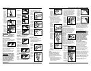
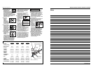
1. Disconnect the
air supply from
the nailer.
2. Remove all
nails from the
magazine (see
Loading/
Unloading).
3.
Make sure the
trigger and
work contact
element (WCE)
move freely up
and down without sticking or binding.
4. Reconnect air
supply to the
nailer.
5. Depress the
Work Contact
Element (WCE)
against the
work surface
without pulling
the trigger. The nailer MUST NOT
OPERATE. Do not use the tool if it
operates without pulling the
trigger. Personal injury may result.
6. Remove the
nailer from the
work surface.
The Work
Contact
Element (WCE)
must return to its original down
position. The nailer MUST NOT
OPERATE. Do not use the tool if it
operates while lifted from the work
surface. Personal injury may result.
7. Pull the
trigger and
depress the
work contact
element
(WCE) against the work surface. The
nailer MUST NOT OPERATE.
8. Depress the
Work
Contact
Element
(WCE)
against the work surface. Pull the
trigger. The nailer MUST OPERATE.
Operating Instructions
4
Grooves
www.chpower.com
2
1
Movement
2
1
1
2
Nail pusher
mechanism
Latch
El mecanismo
del
empujador
de clavos
El
enganche