


BALANCED
INPUT
4v
1v
2v
OUTPUT
250W/8
XLR/PHONE INPUT
Pin 1/SLEEVE:
Pin 2/TIP:
Pin 3/RING:
GND
POS(+)
NEG(–)
WARNING! RISK OF HAZARDOUS ENERGY. MAKE PROPER SPEAKER CONNECTIONS.
SEE OPERATING MANUAL BEFORE USING.
HOME THEATRE SETTINGS
BALANCED INPUT:
SINGLE ENDED INPUT:
See manual for further details.
2V
1V
SENSITIVITY
for 100W @ 8
POLARITY
180
SINGLE ENDED
INPUT
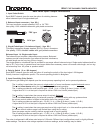
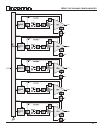
6B/9B AMPLIFIER BRIDGED MODE HOOKUP
6B+9B-BRIDGED-HOOKUP(RP8)PMC.cdr WRP 1 NOV 2002
PUSH
0
BALANCED
INPUT
4v
1v
2v
OUTPUT
250W/8
XLR/PHONE INPUT
Pin 1/SLEEVE:
Pin 2/TIP:
Pin 3/RING:
GND
POS(+)
NEG(–)
WARNING! RISK OF HAZARDOUS ENERGY. MAKE PROPER SPEAKER CONNECTIONS.
SEE OPERATING MANUAL BEFORE USING.
HOME THEATRE SETTINGS
BALANCED INPUT:
SINGLE ENDED INPUT:
See manual for further details.
2V
1V
SENSITIVITY
for 100W @ 8
POLARITY
180
SINGLE ENDED
INPUT
PUSH
0
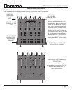
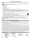
The same signal is fed into both amplifier channel inputs via a “Y” adaptor cable. Note that the POLARITY of
one channel is the inverse of the other. THIS IS ESSENTIAL for the amplifier to operate in bridged mode.
Failure to INVERT one of the channels relative to the other will result in zero output. It does not matter
which channel is set to zero degrees and which one is set to 180 degrees, however, as long as they are
different.
When bridging two channels together the resultant output will be increased by 6 dB relative to the output
of a single channel. To keep the gain of a bridged channel the same as that of a single channel, the
SENSITIVITY switch should be set to a higher voltage setting. For example, if a single channel is set to “1V”
sensitivity, then both the bridged channels would be set to “2V”. Likewise, if a single channel were set to a
sensitivity of “2V”, then the bridged channels would be set to “4V”.
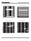
While any two channels can be bridged, we recommend that adjacent channels
be used (as shown) to facilitate the external wiring between the channels.
Note that only the POSITIVE (+) terminals on the 6B power amplifier modules
are connected to the speaker. A ground wire (16g or heavier wire
recommended) must be connected between the two BLACK output terminals
on the 6B amplifier channels being bridged. DO NOT CONNECT ANYTHING ELSE
TO EITHER OF THESE BLACK OUTPUT TERMINALS!
The red (positive) output terminal of the non-inverted channel (the one whose
polarity is set to zero degrees) is connected to the speakers positive (+)
terminal. The red (positive) output terminal of the inverted channel (the one
whose polarity is set to 180 degrees) is connected to the speakers negative (-)
terminal.
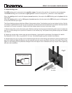
To SOURCE SIGNAL
BALANCED
INPUT
4v
1v
2v
OUTPUT
250W/8
XLR/PHONE INPUT
Pin 1/SLEEVE:
Pin 2/TIP:
Pin 3/RING:
GND
POS(+)
NEG(–)
WARNING! RISK OF HAZARDOUS ENERGY. MAKE PROPER SPEAKER CONNECTIONS.
SEE OPERATING MANUAL BEFORE USING.
HOME THEATRE SETTINGS
BALANCED INPUT:
SINGLE ENDED INPUT:
See manual for further details.
2V
1V
SENSITIVITY
for 100W @ 8
POLARITY
180
SINGLE ENDED
INPUT
PUSH
0
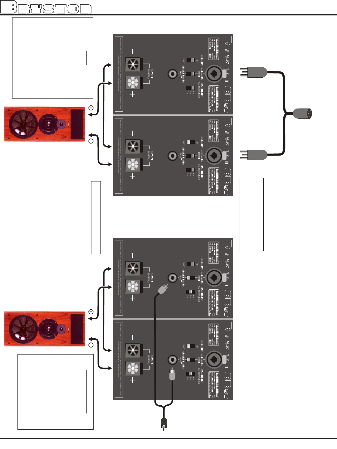
To
SOURCE
SIGNAL
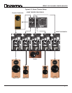
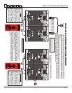
While single ended or unbalanced inputs are used here,
bridging can also be accomplished using the balanced inputs
as shown to the left.
When bridging “PRO” channels which are
equipped with level controls, it is
imperative that the level controls on BOTH
channels being bridged be set to their
maximum clock-wise positions (0 dB).
While balanced inputs are used
here, bridging can also be
accomplished using the single
ended inputs as shown at right.
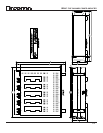
HEAT
When two 6B channels are bridged the
power output can exceed 800 Watts.
Two 9B channels can provide over 300
Watts. When operated at these
elevated power levels there is a
pos sibil ity of the ampli fier
overheating. When overheated they
will automatically be shutdown by
internal protection circuitry to prevent
any damage occurring to the
amplifier. To prevent overheating it
may be necessary to provide external
fan cooling especially if the amplifier
is installed in an enclosed cabinet and
operated at or near maximum power
levels.
BRIDGING KITS
Bryston can supply Bridging Kits
consisting of a “Y” adaptor cable
and a ground strap cable. The “Y”
adaptor cable can be equipped with
either RCA (Phono) connectors
(Part # 150901) for single-ended
applications, or with XLR
connectors (Part #150902) for
balanced applications. The ground
strap cable is equipped with gold
plated spade lug connectors on
either end. Bryston Bridging Kits
are designed for use with adjacent
channels.
ALTHOUGH 6B CHANNELS ARE SHOWN, THE
SAME HOOKUP APPLIES TO 9B CHANNELS
11
9BSST FIVE CHANNEL POWER AMPLIFIER