


6
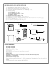
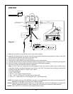
VOD1221
Auxillary
video display
12 VDC Power and Ground
INPUT
VIDEO
(Yellow)
LINE
OUT
VIDEO
Patch Cord
RCA-Female
RCA Male to Male
To Secondary AV Monitor
TO
OPTIONAL
ADDITIONAL
MONITOR
*OPTIONAL RELAY BOX
SIRSWB
*ANTENNA FOR WIRELESS FM MOD
**
See Antenna Note Below
UNIT (BACK VIEW)
TV ANTENNA
To TV Antenna In
PODTVT
CHOKE
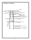
Power Harness
Item #3
Power Harness
Item #3
Dome Light
Power Source
Line Out-R (Red)
Line Out-L (White)
Line Out-V (Yellow)
Red RCA (Audio Right)
Clean the IR Receiver Window on the front of the VCP.
Remove Adhesive Backing and Apply IR LED to IR
Yellow RCA (Video)
White RCA (Audio Left)
"Y" Adapter
for use with
Non-Stereo
Installations
Item# 5
Power Connector
4 Pin
Accessory
Harness - Optional
(P/N:8010730)
DIN 1
DIN 2
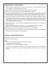
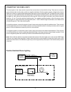
1) Make the connections to the vehicle for the 12 pin wiring harness.
2) Insert the Circular Mini-Din Connector of the source component harness through the wire tie loop on the main
PCB and into the Mini-Din Connector on the main PCB.
3) Pull the wire tie loop tight and cut off the excess.
4) Connect the 12 pin harness to the mating connector on the Video Monitor.
5) Connect power harness to vehicle’s electrical system by tapping into an accessory hot line and a good ground.
6) Verify all functions of the System before final mounting of the finished assembly.
7) Mount and connect the Television antenna. (Optional)
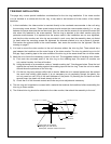
Note: A VCP or other A/V Component can be connected to the video monitor system using a second source
component harness (purchased separately, part number: 8010730). This harness would plug into the Mini-Din
connector on the main PCB as in steps 2 and 3 above.
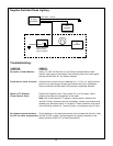
A/V Source Definitions:
1. DVD – Built in DVD
2. AUX-IN – VCP, Game or future DVD etc...
3. AV1 – VCP or VCP with TV Tuner (Mini-Din on main PCB)
4. AV2 or TV – When PODTVT is connecting the unit, TV will replace AV2.
*NOTE: If the original relay box P/N SIRSWB is installed, it recommended that the antenna for the wireless FM
Modulator be unplugged. See Figure A for antenna location.
**NOTE: Extending the wireless antenna beyond its 12 inch length will cause the FM Modulator to exceed FCC
limits for wireless transmission. When installing the unit position the antenna for best reception.
***NOTE: When PODTVT is used the AV2 input position does not work.
Figure A
***PODTVT