


Congratulations on your purchase of the AudioSource
AE4SW Speaker Selector. This product is designed
to distribute stereo music to four independent
listening zones via connection with your existing
audio system.
Please read this Installation Manual to ensure the
proper installation and performance of your AE4SW
Speaker Selector.
AE4SW
4 Zone Stereo Speaker Selector
Function of the AE4SW
The AE4SW is a low-profile speaker-level audio distribution
system with individual On/Off selectors controlling signal
distribution to four listening zones. Pass-through amplifier
input terminals allow easy connection of additional AE-SW
selectors. User-selectable protection circuitry ensures that
the combined speaker load impedance presented to the
amplifier never falls below 6 ohms per channel.
The AE-SW selector is designed to be used independently
or in conjunction with AE100VC Impedance Matching
Volume Controls. These provide independent volume
control for each zone and provide impedance matching
in place of the AE-SW selector.
When using impedance matching volume controls, the
AE-SW protection circuit should be in the off position.
Follow instructions in the AE100VC manual for correct
impedance matching settings.
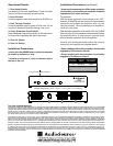
Installation and Connection Precautions
Polarity (+/-) for the input and output speaker terminals
is clearly marked on the AE4SW rear panel. Speaker
wire is coded to identify each conductor as either
positive (+) or negative (-). Maintain (+) to (+) and (-) to (-)
connections between all components in your installation.
1. Route the speaker cables from each speaker zone
and the amplifier to the terminals on the AE-SW. These
terminals will accept up to 10 gauge speaker cable.*
The amplifier cables connect to the terminals marked
“INPUT” on the back of the AE-SW unit. The speaker
cables connect to the numbered Zone output terminals
on the AE-SW selector.
Note: UL rated CL3 speaker wire is recommended when
running wire inside your walls. In many areas it may
be
required by code. To avoid picking up hum and interference
do not install the speaker wire parallel to any 120V power lines.
If the speaker wire needs to cross a 120V power line at
a
right angle this will not create a problem. If you are uncomfortable
with running the speaker wire yourself, it is recommended
that you retain a qualified custom home installation specialist
or electrician.
2. Strip 3/8” of insulation from the end of the cable and
twist the exposed end to avoid fraying.
3. Press the spring-loaded lever on the speaker termin
al
and insert the speaker cable, carefully observing the
polarity.
4. Release the spring loaded lever to clamp the cable
in place. Gently pull on the cable to ensure it’s securely
connected.
5. The system is now ready for testing.
Turn on the
sound system and set the amplifier’s volume control
to a moderate level.
6. Sound should be heard from each zone when it
s
button is depressed. Check each zone for proper left
and right connections by activating each zone with the
balance adjusted to full left and then to full right.
7. Attach the custom die-cut labels provided to th
e
buttons of the AE4SW, referencing each button to its
zone within the installation.
Recommended Speaker Wire Gauges
Excess resistance caused by using an undersized
speaker wire can result in loss of power, loss of bass
definition and loss of overall dynamic range. Over
extremely long wire runs you may even experience a
loss of high frequency content in the audio signal.
To prevent sonic degradation in your speaker installation,
total speaker wire resistance should be kept below
0.5 ohms. The following table lists recommended speaker
wire gauge versus wire run length.
50’ or less - 16 Gauge 2-Cond. CL3 Rated
50’ - 150’ - 12 Gauge 2-Cond. CL3 Rated
150’ - 200’ - 10 Gauge 2-Cond. CL3 Rated
Installation and Connection Procedures
* Use of speaker cable smaller than 16 gauge is not
recommended.