


ASUS P4S800D-X motherboard
1-15
1.10.2 Internal connectors
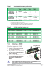
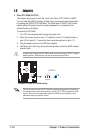
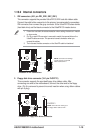
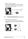
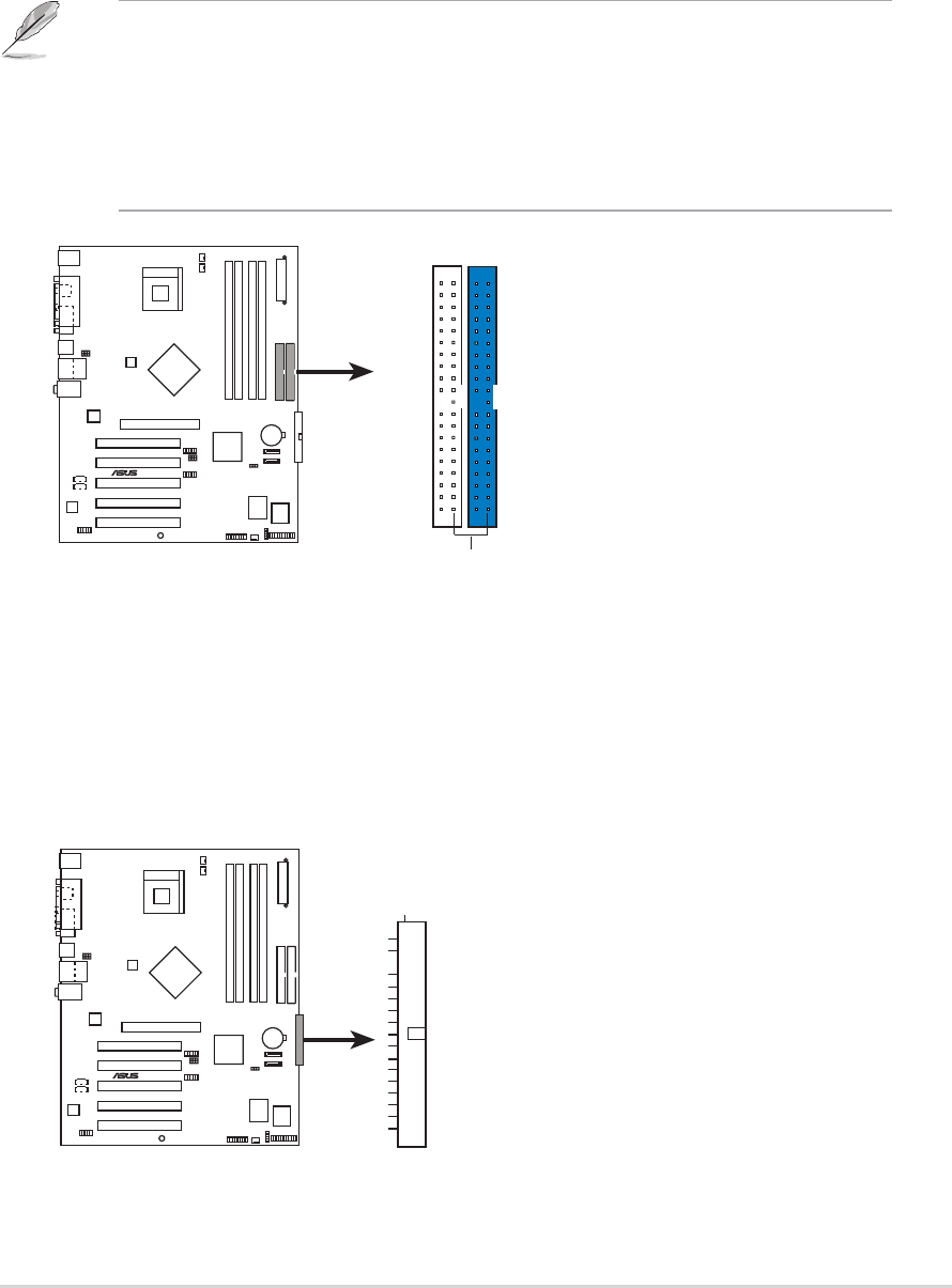
1. IDE connectors (40-1 pin PRI_IDE1, SEC_IDE1)
This connector supports the provided UltraATA133 IDE hard disk ribbon cable.
Connect the cable’s blue connector to the primary (recommended) or secondary
IDE connector, then connect the gray connector to the UltraATA133 slave device
(hard disk drive) and the black connector to the UltraATA133 master device.
1. Follow the hard disk drive documentation when setting the device in master
or slave mode.
2. Pin 20 on each IDE connector is removed to match the covered hole on the
UltraATA cable connector. This prevents incorrect orientation when you
connect the cables.
3. The hole near the blue connector on the UltraATA cable is intentional.
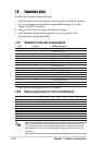
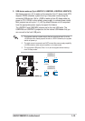
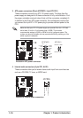
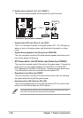
2. Floppy disk drive connector (34-1 pin FLOPPY1)
This connector supports the provided floppy drive ribbon cable. After
connecting one end to the motherboard, connect the other end to the floppy
drive. (Pin 5 is removed to prevent incorrect insertion when using ribbon cables
with pin 5 plug).
P4S800D-X
®
P4S800D-X IDE connectors
NOTE: Orient the red markings
(usually zigzag) on the IDE
ribbon cable to PIN 1.
SEC_IDE1
PRI_IDE1
PIN 1
P4S800D-X
®
P4S800D-X Floppy disk drive connector
NOTE: Orient the red markings on
the floppy ribbon cable to PIN 1.
FLOPPY1
PIN 1